
Examples
Buck regulator
12 V to 3.3 V, with the reasoning kept beside the circuit. The converter itself is ordinary. What is not ordinary is that the argument for it sits in the same graph as the inductor.
The program
Section titled “The program”buck_regulator.py records five kinds of reasoning as
entities, not comments:
rail_tolerance = Requires("The 3V3 rail holds 3.3 V within 3% for 0 to 1.5 A over a 6 to 15 V input", ...)part_choice = Chooses("Which converter makes the 3V3 rail?", selected="TPS62130", ...)ripple_current = Cites("Recommended inductor ripple is 20 to 40% of the maximum output current", ...)inductor_value = Calculates("L = v_out * (1 - v_out / v_in) / (f_sw * ripple_current)", ...)under_load = Simulates("rail_tolerance", measures={"ripple": ..., "output": ...}, ...)So “why is this 4.7 µH?” has an answer the graph can give: a calculation, over a datasheet claim, serving a requirement, which a question verifies. Nobody had to write a design document. Nothing here can drift from the design either, because it is the design. Change the evidence and the decision resting on it is flagged.
The output voltage is deliberately not a parameter of the controller. The feedback divider on the board sets it, which is why the divider carries the constraint that produces it.
The controller’s EN pin is tied to the input, because the rail is always on and
the datasheet says EN must be set high or low rather than left open: an
enable_input citation records where (section 8.3.1, page 9), and the
datasheet’s typical application ties EN to VIN the same way. KiCad’s rules
check reported the pin unconnected while it floated.
The question
Section titled “The question”The requirement used to be closed by a Verifies(..., result="PASS") whose
evidence was two datasheet citations: a citation, not a verification. It is
now a question, and the program cannot state its answer.
ripple and output are parameters with no value, each with a constraint:
ripple at most 30 mV, the output between 3.2 and 3.4 V. The question measures
both on a bench it names in full: 12 V on the controller’s input, 2.2 Ohm
across the rail header (1.5 A at 3.3 V), and a transient to 1.2 ms measured
over its last 0.2 ms. It leaves out the input connector, the fuse, the reverse
diode and the header, so the supply lands on the controller.
The controller is simulated by ideal_buck.sub: two ideal
switches at a fixed duty of 0.275. It is not a model of the TPS62130, and the
program says so: the trait’s provenance is an assumption, which halves the
confidence of every number measured over it, and what it leaves out, the
control loop above all, is recorded as a coverage gap on every run.
out/verification.txt is what fang verify finds:
3.29 V and 1.90 mV of ripple, both inside their constraints, so the
verification passes at confidence 0.5. Those numbers enter the graph as
inferred values whose source is the run’s evidence, through the commit gate,
and the constraints over them are decided by the gate’s own constraint check.
What comes out
Section titled “What comes out”11 parts, 9 nets, 124 entities, 18 checks. None failed and four undecided:
three are the rail’s own numbers, until fang verify measures them.
out/rationale.md is the file to read. It is the whole
argument, projected out of the graph in identifier order:
system.inductor_value (
Section titled “system.inductor_value (CALC-7d60a2e8f772)”CALC-7d60a2e8f772)
L = v_out * (1 - v_out / v_in) / (f_sw * ripple_current)Result: 4.7 uH at 1.25 MHz for 30% ripple at 1.5 A
- Over
system.inductor(Inductor,CMP-64dfc4cd840c)
out/verification.txt: the question, answeredout/buck_regulator.net,out/netlist.txtout/checks.txt,out/graph.txt
Running it
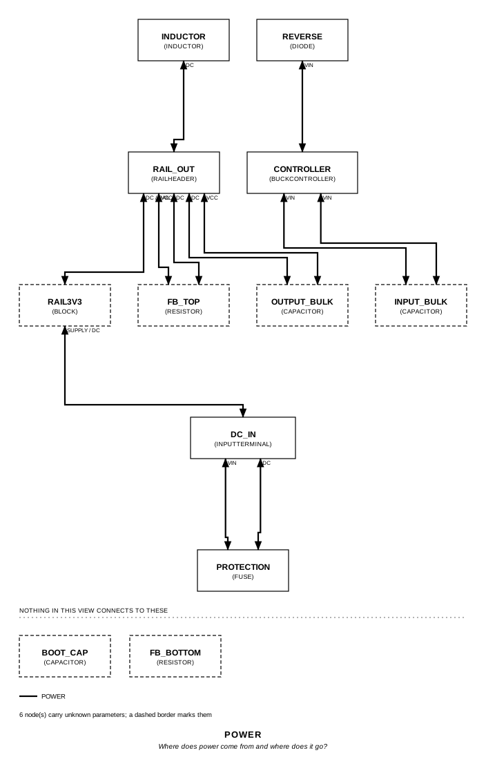
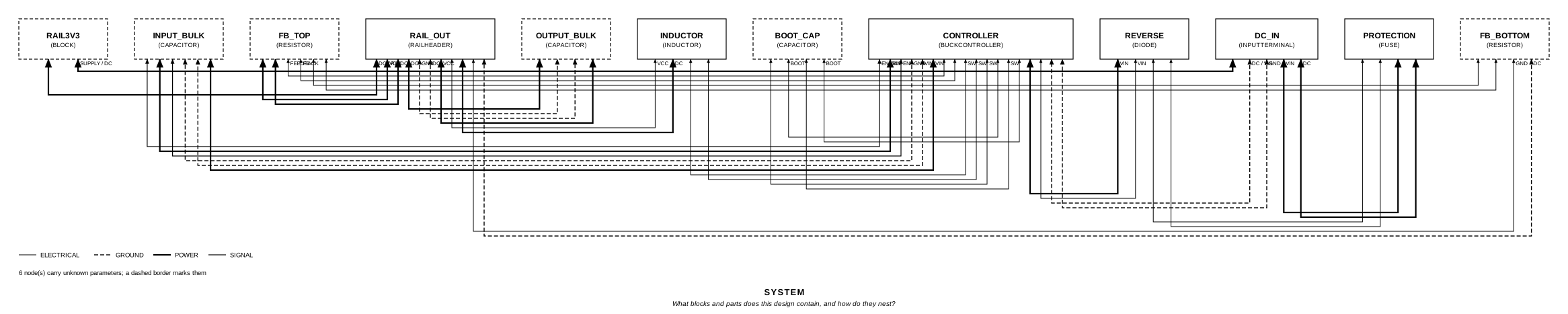
Section titled “Running it”fang check examples/buck_regulator/buck_regulator.pyfang verify examples/buck_regulator/buck_regulator.py # needs ngspicefang view examples/buck_regulator/buck_regulator.py power -o power.svgThe whole program
Section titled “The whole program”"""A 12 V to 3.3 V buck converter, with the reasoning kept beside the circuit.Show 8 more lines
The circuit is ordinary. What is not ordinary is that the requirement, the partdecision, the datasheet numbers behind it, the two calculations, and thequestion that verifies the requirement are all entities in the same graph asthe inductor, so `fang` can answer "why is this 4.7 uH?" without anyone havingwritten a design document, and `fang verify` can find out whether the railholds under load rather than take a hand-written PASS for it."""
from fang.interfaces import AnalogIn, Pin, PinMap, PowerIn, PowerOutfrom fang.lang import ( A, Electrical, Ohm, Parameter, Part, Signal, System, UnitLiteral, V, kHz, kOhm, mA, mOhm, mV, mW, ms, nF, require, uF, uH,)from fang.parts import Capacitor, Diode, Fuse, Inductor, Resistorfrom fang.rationale import Calculates, Chooses, Cites, Requiresfrom fang.simulation import Transientfrom fang.traits import Simulatablefrom fang.verification import Average, PeakToPeak, Simulates, assumed_provenance
#: Dimensionless, for the divider ratio.ratio = UnitLiteral("1")
class BuckController(Part): """A synchronous buck IC: it switches, and it compares against a reference.Show 4 more lines
The output voltage is nowhere on this part. It is set by the divider on the board, which is why the divider carries the constraint that produces it. """
designator_prefix = "U"
vin = PowerIn(voltage=12 * V, current_demand=1500 * mA) sw = Electrical() boot = Electrical() feedback = AnalogIn(voltage=800 * mV) enable = Signal()
input_voltage_max = Parameter("V") reference_voltage = Parameter("V", description="what feedback is compared against") switching_frequency = Parameter("Hz") output_current_max = Parameter("A")
VIN = Pin("VIN", role="power", number="1") GND = Pin("GND", role="ground", number="2") SW = Pin("SW", role="unknown", number="3") BOOT = Pin("BOOT", role="unknown", number="4") FB = Pin("FB", role="analog", number="5") EN = Pin("EN", role="control", number="6")
pinmap = PinMap( { "vin.vcc": "VIN", "vin.gnd": "GND", "sw.line": "SW", "boot.line": "BOOT", "feedback.signal": "FB", "enable.line": "EN", } )
class InputTerminal(Part): """Where the unregulated supply lands."""
designator_prefix = "J"
dc = PowerOut(voltage=12 * V, current_capability=2 * A)
VIN = Pin("VIN", role="power", number="1") GND = Pin("GND", role="ground", number="2")
pinmap = PinMap({"dc.vcc": "VIN", "dc.gnd": "GND"})
class RailHeader(Part): """Where the 3V3 rail leaves for the rest of the board."""
designator_prefix = "J"
dc = PowerIn(voltage=3.3 * V, current_demand=1500 * mA)
VCC = Pin("3V3", role="power", number="1") GND = Pin("GND", role="ground", number="2")
pinmap = PinMap({"dc.vcc": "3V3", "dc.gnd": "GND"})
class Rail3V3(System): """The rail, and the argument for it."""
# -- what the board has to do ----------------------------------------- rail_tolerance = Requires( "The 3V3 rail holds 3.3 V within 3% for 0 to 1.5 A over a 6 to 15 V input", priority="MUST", validation="analysis", )
part_choice = Chooses( "Which converter makes the 3V3 rail?", selected="TPS62130", alternatives=[ {"part": "LM2596", "reason": "asynchronous, and too tall for the enclosure"}, {"part": "MP2315", "reason": "no power-good output, and the sequencing needs one"}, ], requirements=("rail_tolerance",), evidence=("absolute_maximum",), rationale=( "17 V absolute maximum against a 15 V worst case input", "3 A capability against a 1.5 A load, so the part is not the limit", ), )
absolute_maximum = Cites( "VIN absolute maximum is 17 V, recommended operating is 3 to 17 V", document="SRC-DS-TPS62130", locator="section 6.1, absolute maximum ratings", ) ripple_current = Cites( "Recommended inductor ripple is 20 to 40% of the maximum output current", document="SRC-DS-TPS62130", locator="section 9.2.2.1, inductor selection", ) enable_input = Cites( "EN must be set externally High or Low; High starts the converter, Low shuts it down", document="SRC-DS-TPS62130", locator="section 8.3.1, enable / shutdown (EN), page 9", )
# -- the two numbers that were computed, and from what ------------------ inductor_value = Calculates( "L = v_out * (1 - v_out / v_in) / (f_sw * ripple_current)", inputs=("inductor", "controller"), result="4.7 uH at 1.25 MHz for 30% ripple at 1.5 A", requirements=("rail_tolerance",), ) divider_ratio = Calculates( "v_out = v_ref * (1 + top / bottom)", inputs=("fb_top", "fb_bottom"), result="3.3 V from a 0.8 V reference at 3.125", requirements=("rail_tolerance",), )
# -- the circuit -------------------------------------------------------- supply = PowerIn(voltage=12 * V, current_capability=2 * A) rail = PowerOut(voltage=3.3 * V, current_capability=1500 * mA)
# The rail's 3% tolerance, carried back through the divider and declared as # parameters so the comparison has a named thing on its left-hand side. divider_min = Parameter("", default=3.03 * ratio) divider_max = Parameter("", default=3.22 * ratio)
# What the rail does under load. Declared without values: nothing on this # page knows them, and a number written here would be a claim, not a # measurement. `fang verify` measures them. ripple = Parameter("mV", description="peak-to-peak on the rail at full load") output = Parameter("V", description="the rail's average at full load")
dc_in = InputTerminal(package="TerminalBlock_1x02_P5.08mm") rail_out = RailHeader(package="PinHeader_1x02_P2.54mm")
protection = Fuse(current_rating=2 * A, voltage_rating=60 * V, package="F_1206") reverse = Diode( reverse_voltage=100 * V, forward_voltage=550 * mV, forward_current=3 * A, package="SMA", )
controller = BuckController( input_voltage_max=17 * V, reference_voltage=800 * mV, switching_frequency=1250 * kHz, output_current_max=3 * A, package="VQFN-16", )
inductor = Inductor( inductance=4.7 * uH, current_rating=3 * A, dc_resistance=45 * mOhm, package="L_4x4mm", )
input_bulk = Capacitor(capacitance=22 * uF, voltage_rating=50 * V, package="C_1210") output_bulk = Capacitor(capacitance=22 * uF, voltage_rating=16 * V, package="C_1206") boot_cap = Capacitor(capacitance=100 * nF, voltage_rating=16 * V, package="C_0402")
fb_top = Resistor(resistance=200 * kOhm, power_rating=63 * mW, package="R_0402") fb_bottom = Resistor(resistance=64 * kOhm, power_rating=63 * mW, package="R_0402")
# -- and the question that verifies the requirement ----------------------- # Full load at the 12 V nominal input: 2.2 Ohm draws 1.5 A at 3.3 V. The # window starts a millisecond in, once the output filter has settled from # power-up. The input connector, the fuse and the reverse diode are left # out deliberately, so the supply lands on the controller's input; the # rail header is only where the load is applied. under_load = Simulates( "rail_tolerance", measures={ "ripple": PeakToPeak("rail_out.dc", after=1 * ms, until=1.2 * ms), "output": Average("rail_out.dc", after=1 * ms, until=1.2 * ms), }, supplies={"controller.vin": 12 * V}, loads={"rail_out.dc": 2.2 * Ohm}, analysis=Transient(stop="1.2ms", step="10ns"), abstracted=("dc_in", "protection", "reverse", "rail_out"), )
def __init__(self, **overrides): super().__init__(**overrides) self.controller.select( "TI", "TPS62130RGTR", distributor_ids={"lcsc": "C77378"}, datasheet="SRC-DS-TPS62130", ) # The power stage the question runs is an ideal one, and says so: its # provenance is an assumption, which lowers the confidence of every # number measured over it, and what it leaves out is recorded as a # coverage gap on every run. self.controller.add_trait( Simulatable( backends=("ngspice",), source="ideal_buck.sub", pin_map={ "VIN": "vin", "GND": "gnd", "SW": "sw", "BOOT": "boot", "FB": "fb", "EN": "en", }, provenance=assumed_provenance( "an ideal switch pair at a fixed duty, standing in for the TPS62130" ), not_modelled=( "the control loop is not modelled; duty is fixed at 0.275", "no soft start, current limit or switching loss", ), ) )
def architecture(self): # The system's declared edges, and the connectors that realize them. self.supply >> self.dc_in.dc self.rail_out.dc >> self.rail
self.dc_in.dc.vcc >> self.protection.p1 self.protection.p2 >> self.reverse.p1 self.reverse.p2 >> self.controller.vin.vcc self.dc_in.dc.gnd >> self.controller.vin.gnd
self.controller.vin.vcc >> self.input_bulk.p1 self.controller.vin.gnd >> self.input_bulk.p2
# The rail is always on, and EN may not float: it is tied to the # input net, as the datasheet's typical application ties it (figure # 9-1, page 13), which its VIN + 0.3 V maximum allows. It lands on the # input capacitor's pin, since a logic input is no power surface. self.controller.enable >> self.input_bulk.p1
# The switching node: the one net on this board whose loop area matters # more than its schematic. self.controller.sw >> self.inductor.p1 self.controller.sw >> self.boot_cap.p1 self.boot_cap.p2 >> self.controller.boot
self.inductor.p2 >> self.rail_out.dc.vcc self.rail_out.dc.vcc >> self.output_bulk.p1 self.rail_out.dc.gnd >> self.output_bulk.p2
# The divider that actually sets the output, tapped back to feedback. self.rail_out.dc.vcc >> self.fb_top.p1 self.fb_top.p2 >> self.controller.feedback.signal self.fb_top.p2 >> self.fb_bottom.p1 self.fb_bottom.p2 >> self.rail_out.dc.gnd
def constraints(self): # The part has to clear the 15 V worst case, not the 12 V nominal. require(self.controller.input_voltage_max >= 16 * V) require(self.controller.output_current_max >= 1500 * mA)
# 20 to 40% ripple at 1.25 MHz puts the inductor between these bounds. # Both come from the cited selection procedure, not from a preference. require(self.inductor.inductance >= 3.3 * uH) require(self.inductor.inductance <= 10 * uH) require(self.inductor.current_rating >= 2 * A)
# (1 + top / bottom) = 4.125 gives 3.3 V from a 0.8 V reference, so the # ratio itself is what has to hold when either resistor is substituted. division = self.fb_top.resistance / self.fb_bottom.resistance require(self.divider_max >= division) require(self.divider_min <= division)
# The input capacitor sees the input, and a hot-plugged supply rings. require(self.input_bulk.voltage_rating >= 25 * V) require(self.output_bulk.voltage_rating >= 10 * V)
# The rail's 3% at full load, and a ripple the loads can live with. # Undecided until `fang verify` measures them. require(self.ripple <= 30 * mV) require(self.output >= 3.2 * V) require(self.output <= 3.4 * V)The files it writes
Section titled “The files it writes”The parts, then the nets and the pads on them.
C1 100 nF Package:C_0402C2 22 uF Package:C_1210C3 22 uF Package:C_1206D1 550 mV Package:SMAF1 2 A Package:F_1206J1 InputTerminal Package:TerminalBlock_1x02_P5.08mmJ2 RailHeader Package:PinHeader_1x02_P2.54mmL1 4.7 uH Package:L_4x4mmR1 64 kOhm Package:R_0402R2 200 kOhm Package:R_0402U1 BuckController Package:VQFN-16Net-(C1-Pad1) C1.1 L1.1 U1.SWNet-(C1-Pad2) C1.2 U1.BOOTNet-(C2-Pad1) C2.1 D1.K U1.EN U1.VINNet-(C2-Pad2) C2.2 J1.GND U1.GNDNet-(C3-Pad1) C3.1 J2.3V3 L1.2 R2.1Net-(C3-Pad2) C3.2 J2.GND R1.2Net-(D1-PadA) D1.A F1.2Net-(F1-Pad1) F1.1 J1.VINNet-(R1-Pad1) R1.1 R2.2 U1.FBEvery check that ran, and every one left undecided.
UNDECIDED constraint: declared on BLK-42978eb8675aUNDECIDED constraint: declared on BLK-42978eb8675aUNDECIDED constraint: declared on BLK-42978eb8675aUNDECIDED interface_compatibility: current capability is undecided on power_input: current_demand unknown18 checks, 0 failed, 4 undecidedWhat the elaborated graph contains, by entity kind.
1 block 2 calculation 11 component 36 connection 12 constraint 1 decision 3 evidence 5 interface 26 pin 25 port 1 requirement 1 verification 124 totalsnapshot sha256:bfbf58b58b08d039bc8dde706efbd861f5d15f35e60c2fee4b47fa54301ffb74All of it, including the KiCad netlist, is in
examples/buck_regulator/out/. Rebuild it with:
fang build examples/buck_regulator/buck_regulator.py