
Examples / TI op amp handbook / Additional circuits
Rate limiter
SBOA092B page 89, Rate Limiter: an op amp with no feedback of its own comparing EI + EO (summed at its + input through R1 and R0, both 100 kΩ) against ground, a diode bridge fed from ±15 V through R3 and R4 (100 kΩ), and an integrator (R5 100 kΩ, C0 10 µF) whose output is EO and closes the loop.
E_O = -(R_O / R_I) E_I = -E_I, rate limit = 7.5 V/sThe circuit
Section titled “The circuit”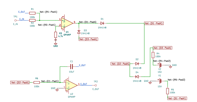
The schematic is drawn by copperhead’s
drafting engine from this circuit’s netlist, with KiCad’s own library symbols,
and it opens in KiCad as figure/rate_limiter.kicad_sch.
The op amp is KiCad’s generic one, since the handbook’s are ideal, and each
terminal is a test point named as the program names it. KiCad reads back from
the sheet exactly the connections the circuit has; draw_figures.py refuses to write
one that does not.
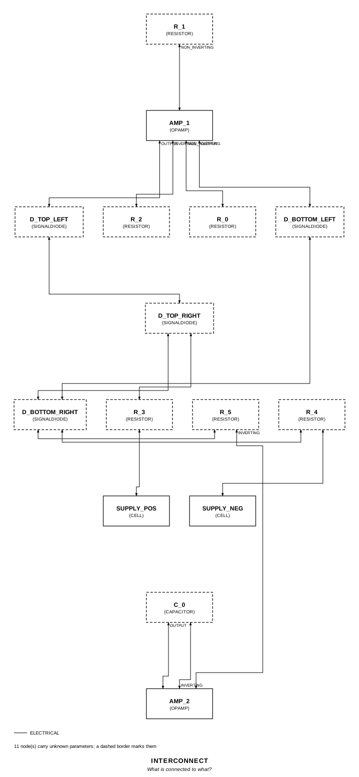
The interconnect view is fang’s own projection. It names the parts as the program does, so it reads against the code below.
What the program says
Section titled “What the program says”The reading (reading) puts R_0 on the first op amp’s + input, where the
integrator’s inversion makes the loop negative, and every bridge diode
pointing from the R_3 corner down to the R_4 corner. The supplies are ±15 V
Cells (supplies). The loop settles at E_I + E_O = 0; while it is away from
there the first op amp sits on a rail, the bridge cuts one side off, and the
integrator gets what R_3 can push through R_5. Two parameters:
require(equals(self.a_v, negative(over(self.r_0.resistance, self.r_1.resistance))))require(equals(self.rate_limit, over(self.supply_pos.voltage, product(total(self.r_3.resistance, self.r_5.resistance), self.c_0.capacitance))))What the simulation found
Section titled “What the simulation found”| Run | Measured | Claimed |
|---|---|---|
settled, E_O / E_I at 2 V | -1 | -1 (a_v), holds |
small_step, E_O after a 0.1 V step | -100 mV | -100 mV, holds |
large_step, slope of E_O after a 5 V step | 7.268 V/s | 7.5 V/s (rate_limit) ± 5%, holds |
large_step, E_O at the end | -5 V | -5 V, holds |
Where the handbook is off
Section titled “Where the handbook is off”A little: 7.5 V/s is 15 V / ((R_3 + R_5) C_0), 75 µA into 10 µF, with no diode drop. The current passes through one bridge diode, which takes about 0.45 V at 73 µA, so the circuit slews at (15 - 0.45) / 200 kΩ / 10 µF = 7.27 V/s, 3% slow. The simulation gives 7.268 V/s. The claim holds the page’s number with a 5% tolerance and says why.
Running it
Section titled “Running it”fang check examples/ti_opamp_handbook/additional/rate_limiter/rate_limiter.pypython examples/regenerate.py ti_opamp_handbook/additional/rate_limiter # needs ngspiceThe whole program
Section titled “The whole program”"""The rate limiter, SBOA092B page 89 (bottom).Show 22 more lines
E_O = -(R_O / R_I) E_I = -E_I, rate limit = 7.5 V/s
Two op amps in one loop. The first has no feedback of its own: E_I through R_1(100 kOhm) and E_O through R_0 (100 kOhm) meet at its + input, and its - inputgoes to ground through R_2 (4.7 kOhm). Whatever E_I + E_O is, it amplifies byits whole open-loop gain. Its output drives a diode bridge, and the bridgedrives the second op amp, an integrator: R_5 (100 kOhm) into the summing pointand C_0 (10 uF) back from E_O.
The bridge is the limit. Its top corner is fed from +15 V through R_3 and itsbottom corner drawn to -15 V through R_4, both 100 kOhm. While the first op ampis near zero, all four diodes conduct and the bridge passes its voltage on.Once it swings to a rail, one side of the bridge is cut off and the currentinto R_5 is whatever R_3 (or R_4) can deliver: about 15 V over R_3 + R_5, 75uA, which C_0 turns into 7.5 V/s. The loop settles when E_I + E_O = 0, whichis E_O = -(R_0/R_1) E_I.
The page names R_0 and R_1 but writes the formula with R_O and R_I, and draws+Supply and -Supply without a value; the program reads the first pair as thesecond and takes +/-15 V (`supplies`)."""
import sysfrom pathlib import Path
# The handbook's shared parts and bench live in the folder above the sections.sys.path.insert(0, str(Path(__file__).resolve().parents[2]))
from fang.lang import Parameter, System, UnitLiteral, V, kOhm, require, uFfrom fang.parts import Capacitor, Resistorfrom fang.rationale import Calculates, Chooses, Citesfrom fang.simulation import OperatingPoint, Transient
from handbook import ( Bench, Cell, Claim, Ground, OpAmp, Run, SignalDiode, Terminal, equals, negative, over, product, ratio, total,)
#: A slew rate.volts_per_second = UnitLiteral("V/s")
class RateLimiter(System): """An open-loop amplifier, a diode bridge, and an integrator, in one loop."""
figure = Cites( "E_O = -(R_O/R_I) E_I = -E_I. Rate limit = 7.5 V/sec", document="SBOA092B, Handbook of Operational Amplifier Applications", locator="page 89, Rate Limiter", )
reading = Chooses( "How is the figure wired?", selected=( "E_I through R_1 to the first op amp's + input, R_0 from E_O back to " "that same + input, R_2 from its - input to ground; the bridge's left " "corner on its output, top corner to +Supply through R_3, bottom to " "-Supply through R_4, right corner through R_5 to the integrator's " "summing point; every diode points from the top corner down to the " "bottom one" ), alternatives=[ { "reading": "R_0 returns to the - input, as a feedback resistor", "reason": ( "R_0's left end drops onto the node where R_1 meets the + " "input; with the integrator inverting, feedback to + is what " "makes the loop negative" ), }, { "reading": "R_2 as the gain-setting resistor of a non-inverting stage", "reason": ( "nothing returns from the first op amp's output to its - " "input; R_2 only returns that input to ground" ), }, ], rationale=( "the loop: E_O too high puts the + input above ground, the first op " "amp rises, the bridge pushes current into the integrator, E_O falls", "the bridge's top two diodes have their anodes on the R_3 corner and " "the bottom two their cathodes on the R_4 corner, which is the " "orientation that limits in both directions", ), )
supplies = Chooses( "What are +Supply and -Supply?", selected="+15 V and -15 V", alternatives=[ { "option": "+/-12 V", "reason": "the 7.5 V/s the page prints is 15 V over R_3 + R_5 and C_0", }, ], rationale=("the handbook's op amps swing +/-13.5 V on +/-15 V supplies",), )
limit = Calculates( "rate = (supply - V_D) / ((R_3 + R_5) C_0)", inputs=("r_3", "r_5", "c_0", "supply_pos"), result=( "the page's 7.5 V/s is 15 V / (200 kOhm x 10 uF), with no diode drop; " "the diode the current passes through costs about 0.45 V at 73 uA, " "so the circuit slews about 3% slower, near 7.27 V/s" ), )
a_v = Parameter("1", default=-1 * ratio, description="E_O / E_I once settled") rate_limit = Parameter( "V/s", default=7.5 * volts_per_second, description="the most E_O can move per second, either way", )
e_in = Terminal() e_out = Terminal() r_1 = Resistor(resistance=100 * kOhm) r_0 = Resistor(resistance=100 * kOhm) r_2 = Resistor(resistance=4.7 * kOhm) amp_1 = OpAmp() d_top_left = SignalDiode() d_top_right = SignalDiode() d_bottom_left = SignalDiode() d_bottom_right = SignalDiode() r_3 = Resistor(resistance=100 * kOhm) r_4 = Resistor(resistance=100 * kOhm) r_5 = Resistor(resistance=100 * kOhm) c_0 = Capacitor(capacitance=10 * uF) amp_2 = OpAmp() supply_pos = Cell(voltage=15 * V) supply_neg = Cell(voltage=15 * V) ground = Ground()
def architecture(self): # The first op amp: E_I and E_O summed at +, - returned to ground. self.e_in.probe >> self.r_1.p1 self.r_1.p2 >> self.amp_1.non_inverting.signal self.amp_1.non_inverting.signal >> self.r_0.p1 self.r_0.p2 >> self.e_out.probe self.amp_1.inverting.signal >> self.r_2.p1 self.r_2.p2 >> self.ground.node
# The bridge. Left corner: the first op amp's output. self.amp_1.output.signal >> self.d_top_left.p2 self.amp_1.output.signal >> self.d_bottom_left.p1 # Top corner: both anodes, fed from +Supply. self.d_top_left.p1 >> self.d_top_right.p1 self.d_top_right.p1 >> self.r_3.p1 self.r_3.p2 >> self.supply_pos.p1 self.supply_pos.p2 >> self.ground.node # Bottom corner: both cathodes, drawn to -Supply. self.d_bottom_left.p2 >> self.d_bottom_right.p2 self.d_bottom_right.p2 >> self.r_4.p1 self.r_4.p2 >> self.supply_neg.p2 self.supply_neg.p1 >> self.ground.node # Right corner: into R_5. self.d_top_right.p2 >> self.d_bottom_right.p1 self.d_bottom_right.p1 >> self.r_5.p1
# The integrator. self.r_5.p2 >> self.amp_2.inverting.signal self.amp_2.inverting.signal >> self.c_0.p1 self.c_0.p2 >> self.amp_2.output.signal self.amp_2.output.signal >> self.e_out.probe self.amp_2.non_inverting.signal >> self.ground.node
def constraints(self): require(equals(self.a_v, negative(over(self.r_0.resistance, self.r_1.resistance)))) require( equals( self.rate_limit, over( self.supply_pos.voltage, product(total(self.r_3.resistance, self.r_5.resistance), self.c_0.capacitance), ), ) )
BENCH = Bench( page=89, title="Rate Limiter", runs=[ Run( "settled", OperatingPoint(), drive={"e_in": "DC 2"}, measure={"gain": "v({e_out.1}) / v({e_in.1})"}, claims=[Claim("gain", "a_v", within=0.001)], ), Run( "small_step", Transient(stop="0.3", step="100u"), drive={"e_in": "PWL(0 0 0.1 0 0.1001 0.1)"}, measure={ "e_before": "find v({e_out.1}) at=0.09", "e_after": "avg v({e_out.1}) from=0.2 to=0.3", "t_half": "when v({e_out.1})=-0.05 fall=1", }, claims=[ Claim("e_after", -0.1, within=0.002, unit="V", note="-E_I for a 0.1 V step, averaged over the last 0.1 s"), ], units={"e_before": "V", "t_half": "s"}, note=( "E_I steps from 0 to 0.1 V at 0.1 s. At the limit that is a 14 ms " "ramp, so E_O is settled well before 0.2 s." ), ), Run( "large_step", Transient(stop="1.2", step="200u"), drive={"e_in": "PWL(0 0 0.1 0 0.1001 5)"}, measure={ "t_minus_1": "when v({e_out.1})=-1 fall=1", "t_minus_4": "when v({e_out.1})=-4 fall=1", "slew": "3 / (t_minus_4 - t_minus_1)", "e_final": "avg v({e_out.1}) from=1.1 to=1.2", }, claims=[ Claim("slew", "rate_limit", within=0.05, unit="V/s", note="the page's 7.5 V/s is 15 V / ((R_3 + R_5) C_0); the " "diode in the path takes about 0.45 V of the 15, so the " "circuit slews about 3% slower"), Claim("e_final", -5, within=0.002, unit="V", note="and it arrives at -E_I"), ], units={"t_minus_1": "s", "t_minus_4": "s"}, note=( "E_I steps from 0 to 5 V at 0.1 s. The slope is timed between " "E_O = -1 V and -4 V, well clear of both ends of the ramp." ), ), ],)The files it writes
Section titled “The files it writes”The parts, then the nets and the pads on them.
C1 10 uF -D1 SignalDiode -D2 SignalDiode -D3 SignalDiode -D4 SignalDiode -GND1 Ground -R1 100 kOhm -R2 100 kOhm -R3 4.7 kOhm -R4 100 kOhm -R5 100 kOhm -R6 100 kOhm -TP1 Terminal -TP2 Terminal -U1 OpAmp -U2 OpAmp -V1 15 V -V2 15 V -Net-(C1-Pad1) C1.1 R6.2 U2.IN-Net-(C1-Pad2) C1.2 R1.2 TP2.1 U2.OUTShow 10 more lines
Net-(D1-PadA) D1.A D3.K U1.OUTNet-(D1-PadK) D1.K D2.K R5.1Net-(D2-PadA) D2.A D4.K R6.1Net-(D3-PadA) D3.A D4.A R4.1Net-(GND1-Pad1) GND1.1 R3.2 U2.IN+ V1.+ V2.-Net-(R1-Pad1) R1.1 R2.2 U1.IN+Net-(R2-Pad1) R2.1 TP1.1Net-(R3-Pad1) R3.1 U1.IN-Net-(R4-Pad2) R4.2 V2.+Net-(R5-Pad2) R5.2 V1.-Every check that ran, and every one left undecided.
2 checks, 0 failed, 0 undecidedWhat the elaborated graph contains, by entity kind.
1 block 1 calculation 18 component 46 connection 2 constraint 2 decision 1 evidence 3 interface 35 pin 35 port 144 totalsnapshot sha256:a939b2b91975d1566a671f922ee7bb25874216fec83178a345c9c79f19f31fedAll of it, including the KiCad netlist, is in
examples/ti_opamp_handbook/additional/rate_limiter/out/. Rebuild it with:
fang build examples/ti_opamp_handbook/additional/rate_limiter/rate_limiter.py