
Examples / TI op amp handbook / Integrators
AC integrator
SBOA092B page 59, AC Integrator: EI through RI (100 kΩ) to the - input, CO (0.01 µF) and a reset switch to the output. The op amp is drawn with two outputs. The one at the top is EO. The bubbled one at the bottom drives R2 (100 kΩ) to the + input, with CI (100 µF) from there to ground. "Integrates AC component only." There is no formula.
The circuit
Section titled “The circuit”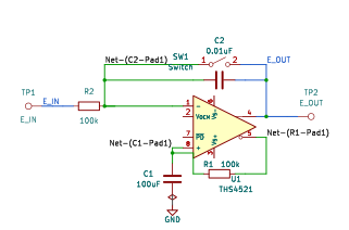
The schematic is drawn by copperhead’s
drafting engine from this circuit’s netlist, with KiCad’s own library symbols,
and it opens in KiCad as figure/ac_integrator.kicad_sch.
The op amp is KiCad’s generic one, since the handbook’s are ideal, and each
terminal is a test point named as the program names it. KiCad reads back from
the sheet exactly the connections the circuit has; draw_figures.py refuses to write
one that does not.
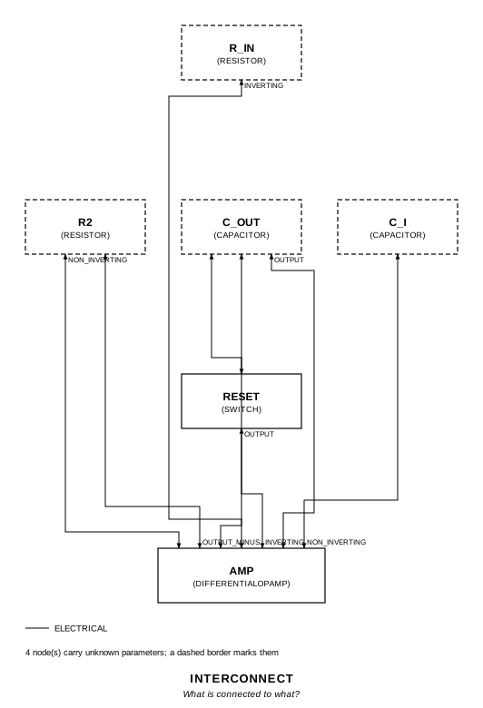
The interconnect view is fang’s own projection. It names the parts as the program does, so it reads against the code below.
What the program says
Section titled “What the program says”The program reads the bubble as an inverted output (reading), so the op amp
is a differential-output part (DifferentialOpAmp). R2 and C_I then
low-pass -E_O onto the + input, which makes them a DC servo. With
τ1 = R_I C_O = 1 ms and τ2 = R2 C_I = 10 s:
E_O/E_I = -(1 + p τ2) / (1 + 2p τ1 + p² τ1 τ2)That is -1 at DC and -1/(p τ1), an integrator, above the corner at
1/(2π √(τ1 τ2)) = 1.59 Hz. The program rejects two other readings. If the
bubble were the same output, the feedback would be positive and would put a
pole in the right half-plane. If R2 and C_I were only a bias return, the
circuit would be a plain integrator that ramps on DC. The parameters are
f_unity = 159.15 Hz, f_corner = 1.5915 Hz and q = 50, all held to the
parts.
What the simulation found
Section titled “What the simulation found”out/simulation.txt, from the decks under out/spice/:
| Run | Measured | Claimed |
|---|---|---|
dc, E_O/E_I for 1 V DC | -1 | -1, holds |
sine, gain at 159 Hz | 1 | 1, holds |
sine, gain at 100 Hz | 1.592 | 1.5915, holds |
sine, phase at 100 Hz | 90.01° | 90°, holds |
sine, gain at 1 mHz | 1.002 | 1.002, holds |
sine, peak | 4573 at 1.585 Hz | not a claim |
ac_on_dc, 0.1 V DC + 0.1 V at 100 Hz, output peak to peak | 318.6 mV | 318.3 mV, holds |
ac_on_dc, output average | -100 mV | -100 mV, holds |
dc_step, 10 mV step, output at 100 s | -10.03 mV | -10 mV, holds |
A DC input comes out inverted and does not ramp. A plain integrator with the same R_I C_O would be at a rail within a second.
What the handbook does not say
Section titled “What the handbook does not say”The drawn values put a resonance at the corner with a Q of 50. A 10 mV DC
step rings at 1.6 Hz up to about ±1 V and takes tens of seconds to settle
(dc_step, e_min and e_max). The ac_on_dc run starts its capacitors at
their steady-state values with .ic so the resonance is barely excited. That
card names the op amp model’s internal node (xu1.xhalf.n1), because the
model’s outputs are ideal sources that ignore an initial condition.
Running it
Section titled “Running it”fang check examples/ti_opamp_handbook/integrators/ac_integrator/ac_integrator.pypython examples/regenerate.py ti_opamp_handbook/integrators/ac_integrator # needs ngspiceThe whole program
Section titled “The whole program”"""The AC integrator, SBOA092B page 59 (bottom).Show 23 more lines
"Integrates AC component only."
E_I reaches the - input through R_I (100 kOhm), with C_O (0.01 uF) and a resetswitch from there to the output. The odd part of the drawing is the op amp: ithas two outputs, a plain one at the top that is E_O and feeds C_O, and abubbled one at the bottom that drives R2 (100 kOhm) to the + input, with C_I(100 uF) from the + input to ground. The page gives no formula.
The program reads the bubble as an inverted output (`reading`): the op amp is adifferential-output part, and R2 and C_I low-pass -E_O onto the + input, a DCservo. Then, with tau_1 = R_I C_O = 1 ms and tau_2 = R2 C_I = 10 s,
E_O/E_I = -(1 + p tau_2) / (1 + 2 p tau_1 + p^2 tau_1 tau_2)
At DC this is -1: a DC input is passed inverted, not integrated, and the outputdoes not ramp. Well above the corner it is -1/(p tau_1), the integrator,-1/(2 pi f R_I C_O) in magnitude. The two meet at a resonance at1/(2 pi sqrt(tau_1 tau_2)) = 1.59 Hz with a Q of sqrt(tau_2/tau_1)/2 = 50,which is what the drawn values give and which the handbook does not mention: aDC step makes the output ring at 1.6 Hz for tens of seconds before it settlesat -E_I."""
import sysfrom pathlib import Path
# The handbook's shared parts and bench live in the folder above the sections.sys.path.insert(0, str(Path(__file__).resolve().parents[2]))
from fang.lang import Hz, Parameter, System, kOhm, require, uFfrom fang.parts import Capacitor, Resistorfrom fang.rationale import Calculates, Chooses, Citesfrom fang.simulation import ACSweep, OperatingPoint, Transient
from handbook import ( TWO_PI, Bench, Claim, DifferentialOpAmp, Ground, Run, Switch, Terminal, corner, over, product, ratio, within,)
class AcIntegrator(System): """An integrator whose + input follows the inverted output, low-passed by R2 and C_I."""
figure = Cites( "Integrates AC component only.", document="SBOA092B, Handbook of Operational Amplifier Applications", locator="page 59, AC Integrator", )
reading = Chooses( "What is the bubbled output at the bottom of the op amp, and what do R2 and C_I do?", selected=( "an inverted output (the op amp has complementary outputs); R2 and C_I " "low-pass -E_O onto the + input, a DC servo that holds the DC gain at -1" ), alternatives=[ { "reading": "the same output as E_O, drawn twice", "reason": ( "then R2 and C_I feed +E_O back to the + input, positive feedback " "at DC: the transfer function has a pole at +1/sqrt(tau_1 tau_2) " "and the output runs to a rail" ), }, { "reading": "R2 and C_I as a bias-current return only, the + input otherwise at ground", "reason": ( "that is an ordinary integrator, which ramps on a DC input; it " "cannot integrate the AC component only" ), }, ], rationale=( "only the inverted reading makes the stated function true: DC gain -1, " "integration above the corner", "the handbook uses op amps with two outputs elsewhere (page 69), and a " "bubble is the usual mark of the inverting one", ), )
response = Calculates( "E_O/E_I = -(1 + p R2 C_I) / (1 + 2 p R_I C_O + p^2 R_I C_O R2 C_I)", inputs=("r_in", "c_out", "r2", "c_i"), result=( "-1 at DC; -1/(p R_I C_O) above the corner, unity gain at 159 Hz and " "1.59 at 100 Hz; a resonance at 1.59 Hz with Q = 50, whose peak the " "AC sweep shows near 5000" ), )
f_unity = Parameter( "Hz", default=159.15 * Hz, description="where the integrator's gain 1/(2 pi f R_I C_O) is 1", ) f_corner = Parameter( "Hz", default=1.5915 * Hz, description="1/(2 pi sqrt(R_I C_O R2 C_I)): below it the circuit stops integrating", ) q = Parameter("1", default=50 * ratio, description="sqrt(R2 C_I / (R_I C_O)) / 2, the corner's Q")
e_in = Terminal() e_out = Terminal() r_in = Resistor(resistance=100 * kOhm) c_out = Capacitor(capacitance=0.01 * uF) reset = Switch() r2 = Resistor(resistance=100 * kOhm) c_i = Capacitor(capacitance=100 * uF) amp = DifferentialOpAmp() ground = Ground()
def architecture(self): self.e_in.probe >> self.r_in.p1 self.r_in.p2 >> self.amp.inverting.signal self.amp.inverting.signal >> self.c_out.p1 self.c_out.p1 >> self.reset.p1 self.c_out.p2 >> self.amp.output.signal self.reset.p2 >> self.amp.output.signal self.amp.output.signal >> self.e_out.probe # The bubbled output, through R2 to the + input, C_I to ground. self.amp.output_minus.signal >> self.r2.p1 self.r2.p2 >> self.amp.non_inverting.signal self.amp.non_inverting.signal >> self.c_i.p1 self.c_i.p2 >> self.ground.node
def constraints(self): tau_1 = product(self.r_in.resistance, self.c_out.capacitance) tau_2 = product(self.r2.resistance, self.c_i.capacitance) require(within(self.f_unity, corner(self.r_in.resistance, self.c_out.capacitance), 0.0001)) # Squared, so no square root is needed: f^2 = 1/((2 pi)^2 tau_1 tau_2). require( within( product(self.f_corner, self.f_corner), over(1 * ratio, product(TWO_PI, TWO_PI, tau_1, tau_2)), 0.0002, ) ) require(within(product(self.q, self.q), over(tau_2, product(4 * ratio, tau_1)), 0.0001))
BENCH = Bench( page=59, title="AC Integrator", runs=[ Run( "dc", OperatingPoint(), drive={"e_in": "DC 1"}, measure={"dc_gain": "v({e_out.1}) / v({e_in.1})", "plus_input": "v({amp.IN+})"}, claims=[Claim("dc_gain", -1, within=0.001, note="a DC input comes out inverted, not integrated: nothing ramps")], units={"plus_input": "V"}, note="E_I = 1 V DC. C_I has charged to -E_O, and the - input follows it to E_I.", ), Run( "sine", ACSweep(points=50, start="1m", stop="100k"), drive={"e_in": "DC 0 AC 1"}, measure={ "gain_unity": "find vm({e_out.1}) at=159.155", "gain_100hz": "find vm({e_out.1}) at=100", "phase_rad": "find vp({e_out.1}) at=100", "phase_deg": "phase_rad * 180 / pi", "gain_1mhz": "find vm({e_out.1}) at=0.001", "peak": "max vm({e_out.1})", "f_peak": "when vm({e_out.1})=peak", }, claims=[ Claim("gain_unity", 1, within=0.001, note="1/(2 pi f_unity R_I C_O) = 1"), Claim("gain_100hz", 1.5915, within=0.001, note="1/(2 pi 100 Hz x 1 ms)"), Claim("phase_deg", 90, within=0.1, absolute=True, note="an inverting integrator: the output leads the input by 90 degrees"), Claim("gain_1mhz", 1.002, within=0.001, note="at 1 mHz the circuit is back to its DC gain of 1 (|1 + j 2 pi f tau_2| = 1.002)"), ], units={"f_peak": "Hz"}, note=( "Above the 1.59 Hz corner the circuit integrates; below it the gain " "returns to 1. The peak at the corner is the Q of 50 the drawn values " "give; it is not a handbook claim." ), ), Run( "ac_on_dc", Transient(stop="1.1", step="10u"), drive={"e_in": "SIN(0.1 0.1 100 0 0 90)"}, # The op amp's outputs are ideal sources, so an initial condition on # them is ignored; the state to set is the model's internal node, which # ngspice names through the instances, XU1 then XHALF. cards=[".ic v(xu1.xhalf.n1)=-0.2 v({amp.IN-})=0.1"], measure={ "e_pp": "pp v({e_out.1}) from=1.0 to=1.03", "e_avg": "avg v({e_out.1}) from=0.4 to=1.03", }, claims=[ Claim("e_pp", 0.31831, within=0.01, unit="V", note=( "0.1 V at 100 Hz integrated: 2 x 0.1/(2 pi 100 Hz x 1 ms). 1%: " "the start is close to the steady state, not exactly on it, " "and what is left rings at 1.6 Hz under the 100 Hz wave" )), Claim("e_avg", -0.1, within=0.003, absolute=True, unit="V", note="the 0.1 V DC component passes at -1 and does not ramp"), ], note=( "0.1 V DC plus a 0.1 V, 100 Hz cosine. The capacitors start where " "the steady state puts them at t = 0 (the `.ic`), so the 1.6 Hz " "resonance is barely rung. The swing is read over 1.0 to 1.03 s; the average over 0.4 to 1.03 s, 63 cycles " "of the input and one period of that resonance." ), ), Run( "dc_step", Transient(stop="100", step="1m"), drive={"e_in": "PWL(0 0 10m 0 10.001m 0.01)"}, measure={ "e_min": "min v({e_out.1}) from=0 to=100", "e_max": "max v({e_out.1}) from=0 to=100", "e_100s": "find v({e_out.1}) at=100", }, claims=[ Claim("e_100s", -0.01, within=0.5e-3, absolute=True, unit="V", note=( "an ordinary integrator would be at -1000 V (a rail) by now; " "this one has settled at -E_I" )), ], units={"e_min": "V", "e_max": "V"}, note=( "A 10 mV DC step at 10 ms, from rest. The output rings at 1.6 Hz " "(the Q of 50) and settles at -10 mV with a 10 s time constant; " "the swing it reaches first is in e_min and e_max." ), ), ],)The files it writes
Section titled “The files it writes”The parts, then the nets and the pads on them.
C1 100 uF -C2 0.01 uF -GND1 Ground -R1 100 kOhm -R2 100 kOhm -SW1 Switch -TP1 Terminal -TP2 Terminal -U1 DifferentialOpAmp -Net-(C1-Pad1) C1.1 R1.2 U1.IN+Net-(C1-Pad2) C1.2 GND1.1Net-(C2-Pad1) C2.1 R2.2 SW1.1 U1.IN-Net-(C2-Pad2) C2.2 SW1.2 TP2.1 U1.OUT+Net-(R1-Pad1) R1.1 U1.OUT-Net-(R2-Pad1) R2.1 TP1.1Every check that ran, and every one left undecided.
3 checks, 0 failed, 0 undecidedWhat the elaborated graph contains, by entity kind.
1 block 1 calculation 9 component 22 connection 3 constraint 1 decision 1 evidence 3 interface 17 pin 17 port 75 totalsnapshot sha256:262f4e219d3efe34486e49176be654df9e2b9af49f7a780f3e4e9449ee5819bdAll of it, including the KiCad netlist, is in
examples/ti_opamp_handbook/integrators/ac_integrator/out/. Rebuild it with:
fang build examples/ti_opamp_handbook/integrators/ac_integrator/ac_integrator.py