
Examples / TI op amp handbook / Additional circuits
AC to DC converter
SBOA092B page 88, AC to DC Converter: a precision half-wave rectifier (R1, R2, R4, all 10 kΩ, two diodes) and a summer with a filter across it: EI through R3 (10 kΩ), the half-wave through R6 (5 kΩ), R7 (10 kΩ) and a 2 kΩ rheostat R8 back from the output, and C (100 µF) across both.
E_O average = 0.9 E_I rms, E_I = 6 mV to 6 V rms at 10 to 1000 HzThe circuit
Section titled “The circuit”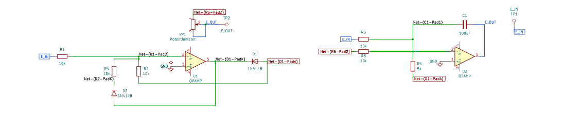
The schematic is drawn by copperhead’s
drafting engine from this circuit’s netlist, with KiCad’s own library symbols,
and it opens in KiCad as figure/ac_to_dc_converter.kicad_sch.
The op amp is KiCad’s generic one, since the handbook’s are ideal, and each
terminal is a test point named as the program names it. KiCad reads back from
the sheet exactly the connections the circuit has; draw_figures.py refuses to write
one that does not.
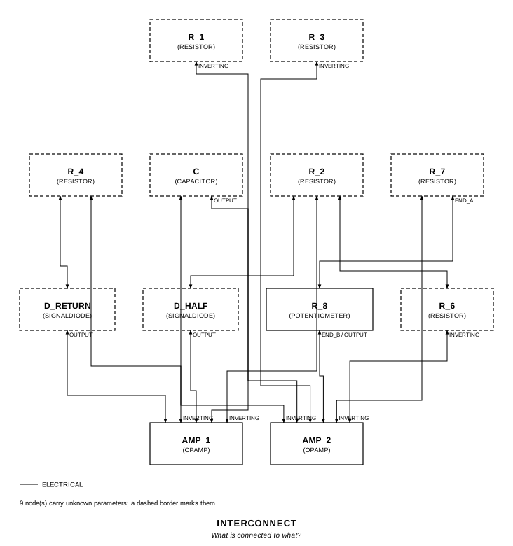
The interconnect view is fang’s own projection. It names the parts as the program does, so it reads against the code below.
What the program says
Section titled “What the program says”The half-wave is -E_I while E_I is positive. Through R_6, half of R_3, it
counts twice, so the summer sees -|E_I| / R_3 on both halves: a full-wave
rectifier, as the page says, whose output C averages. The mean of a full-wave
rectified sine is 2√2/π = 0.9003 of its rms, so a gain of exactly 1 is what
the 0.9 asks for. The program records its reading of the figure (reading),
sets R_8 to zero (trim: it only adds to R_7, so it trims the gain up for
resistors that come out low, and the simulated ones do not), and holds
require(within(self.k_avg, product(SINE_AVERAGE_OVER_RMS, self.gain), 0.001))with gain = (R_7 + R_8') / R_3 and a constraint that R_6’s weight is twice
R_3’s. C against R_7 is 1 s, so each run lasts 10 s and the average is taken
over the last one, with no initial condition to help it along.
What the simulation found
Section titled “What the simulation found”out/simulation.txt, E_I a 100 Hz sine:
| Run | E_O average | E_O avg / E_I rms | Claimed |
|---|---|---|---|
six_volts, 6 V rms | 5.400 V | 0.900 | 0.9 (k_avg) ± 0.1%, holds |
six_millivolts, 6 mV rms | 5.365 mV | 0.894 | 0.9 ± 1%, holds |
At 6 mV the signal current through R_1 is under 1 µA, and the 1N4148 model’s 2.5 nA saturation current through the diode that should be off, with the junction charge moved at each zero crossing, takes 0.6% of it. The looser tolerance there is that, and is said beside the claim.
Running it
Section titled “Running it”fang check examples/ti_opamp_handbook/additional/ac_to_dc_converter/ac_to_dc_converter.pypython examples/regenerate.py ti_opamp_handbook/additional/ac_to_dc_converter # needs ngspiceThe whole program
Section titled “The whole program”"""The AC to DC converter, SBOA092B page 88 (bottom).Show 20 more lines
E_O average = 0.9 E_I rms, E_I = 6 mV to 6 V rms at 10 to 1000 Hz
Two stages. The first is a precision half-wave rectifier: E_I through R_1 intothe summing point, R_2 back from a diode that conducts when the output falls,R_4 back through a diode that conducts when it rises. The half-wave E_H istaken at the R_2 end, so E_H = -E_I while E_I is positive and zero otherwise.
The second stage is a summer with a filter across it: E_I through R_3(10 kOhm) and E_H through R_6 (5 kOhm) into the summing point, R_7 (10 kOhm)and the rheostat R_8 (2 kOhm) back from the output, and C (100 uF) across both.E_H counts twice as much as E_I, so the current into the summing point is-|E_I| / R_3 on both halves, and the output is the full-wave rectified input,times (R_7 + R_8') / R_3, averaged by the filter.
The average of a full-wave rectified sine is 2 sqrt(2) / pi = 0.9003 times itsrms, so a gain of exactly 1 is what the page's 0.9 asks for. R_8 trims thegain up from there to cover the resistors' tolerances; with the drawn valuesexact, the program sets it to zero (`trim`)."""
import sysfrom decimal import Decimalfrom pathlib import Path
# The handbook's shared parts and bench live in the folder above the sections.sys.path.insert(0, str(Path(__file__).resolve().parents[2]))
from fang.lang import Parameter, System, kOhm, require, uFfrom fang.parts import Capacitor, Resistorfrom fang.rationale import Calculates, Chooses, Citesfrom fang.simulation import Transient
from handbook import ( Bench, Claim, Ground, OpAmp, Potentiometer, Run, SignalDiode, Terminal, equals, over, product, ratio, total, within,)
#: The mean of a full-wave rectified sine over its rms: 2 sqrt(2) / pi.SINE_AVERAGE_OVER_RMS = ratio("0.9003163161571062")
class AcToDcConverter(System): """A precision half-wave, and a filtered summer that adds it twice to E_I."""
figure = Cites( "E_O average = 0.9 E_I rms. E_I = 6 mV to 6 V rms @ 10 to 1000 Hz. " "Precision conversion for measurement or control. Full wave rectifier " "with a smoothing filter.", document="SBOA092B, Handbook of Operational Amplifier Applications", locator="page 88, AC to DC Converter", )
reading = Chooses( "How is the figure wired?", selected=( "R_3 runs from E_I to the second summing point; R_1 from E_I to the " "first; R_2 from the first summing point to a node whose diode points " "down into the first op amp's output, and R_6 from that node to the " "second summing point; R_4 returns through a diode pointing left, " "from the output; R_7 and R_8 in series, with C across them, from the " "second summing point to E_O" ), alternatives=[ { "reading": "E_H taken at the R_4 end", "reason": ( "R_6 leaves from the junction of R_2 and the downward diode; " "R_4's diode joins the output below it" ), }, ], rationale=( "under this reading E_H is -E_I for E_I > 0, and R_6 = R_3 / 2 makes " "the sum -|E_I| / R_3 on both halves: a full wave, as the page says", ), )
trim = Chooses( "Where is the rheostat R_8 set?", selected="at zero, so the feedback is R_7 alone and the gain is exactly 1", alternatives=[ { "option": "mid-travel, 1 kOhm", "reason": ( "a gain of 1.1, which reads 0.99 E_I rms: 10% high with " "the drawn resistors exact" ), }, ], rationale=( "the full-wave average is already 0.9003 of the rms at unity gain", "R_8 only adds to R_7, so it is there to trim up for resistors that " "come out low; the simulated ones do not", ), )
bench = Chooses( "How long does the filter take, and what is E_I?", selected=( "a 100 Hz sine at 6 V rms and at 6 mV rms, each run for 10 s, with " "the average taken over the last second" ), alternatives=[ { "option": "an initial condition on C at the expected output", "reason": "it would assume the answer the run is there to check", }, { "option": "1 kHz", "reason": "ten times as many cycles to step through for the same settling", }, ], rationale=( "C against R_7 is 1 s; after 9 s the start-up error is e^-9, about 0.01%", "100 Hz is inside the page's 10 to 1000 Hz, and the ripple at 200 Hz " "through a 1 s filter is a few tenths of a millivolt per volt", ), )
average = Calculates( "E_O average / E_I rms = (2 sqrt(2) / pi) (R_7 + R_8') / R_3", inputs=("r_3", "r_7", "r_8"), result="0.9003 with R_8 at zero, which the page prints as 0.9", )
k_avg = Parameter( "1", default=Decimal("0.9") * ratio, description="E_O average / E_I rms", ) gain = Parameter( "1", default=1 * ratio, description="(R_7 + R_8') / R_3: the full-wave gain before the filter", )
e_in = Terminal() e_out = Terminal() r_1 = Resistor(resistance=10 * kOhm) r_2 = Resistor(resistance=10 * kOhm) r_4 = Resistor(resistance=10 * kOhm) d_half = SignalDiode() d_return = SignalDiode() amp_1 = OpAmp() r_3 = Resistor(resistance=10 * kOhm) r_6 = Resistor(resistance=5 * kOhm) r_7 = Resistor(resistance=10 * kOhm) r_8 = Potentiometer(resistance=2 * kOhm, setting=0 * ratio) c = Capacitor(capacitance=100 * uF) amp_2 = OpAmp() ground = Ground()
def architecture(self): # The half-wave stage. self.e_in.probe >> self.r_1.p1 self.r_1.p2 >> self.amp_1.inverting.signal self.amp_1.non_inverting.signal >> self.ground.node self.amp_1.inverting.signal >> self.r_2.p1 self.r_2.p2 >> self.d_half.p1 self.d_half.p2 >> self.amp_1.output.signal self.amp_1.inverting.signal >> self.r_4.p1 self.r_4.p2 >> self.d_return.p2 self.d_return.p1 >> self.amp_1.output.signal
# The summer and its filter. self.e_in.probe >> self.r_3.p1 self.r_3.p2 >> self.amp_2.inverting.signal self.r_2.p2 >> self.r_6.p1 self.r_6.p2 >> self.amp_2.inverting.signal self.amp_2.inverting.signal >> self.r_7.p1 self.r_7.p2 >> self.r_8.end_a self.r_8.wiper >> self.r_8.end_b self.r_8.end_b >> self.amp_2.output.signal self.amp_2.inverting.signal >> self.c.p1 self.c.p2 >> self.amp_2.output.signal self.amp_2.output.signal >> self.e_out.probe self.amp_2.non_inverting.signal >> self.ground.node
def constraints(self): # Full wave: the half-wave's weight through R_6 is twice E_I's through R_3. require( equals( over(self.r_2.resistance, product(self.r_1.resistance, self.r_6.resistance)), over(2 * ratio, self.r_3.resistance), ) ) require( equals( self.gain, over( total(self.r_7.resistance, product(self.r_8.resistance, self.r_8.setting)), self.r_3.resistance, ), ) ) # The page rounds 0.9003 to 0.9. require(within(self.k_avg, product(SINE_AVERAGE_OVER_RMS, self.gain), 0.001))
def _run(name: str, rms: str, peak: str, within: float, why: str, note: str) -> Run: return Run( name, Transient(stop="10", step="50u"), drive={"e_in": f"SIN(0 {peak} 100)"}, measure={ "e_average": "avg v({e_out.1}) from=9 to=10", "ripple": "pp v({e_out.1}) from=9 to=10", "k_measured": f"e_average / {rms}", }, claims=[ Claim("k_measured", "k_avg", within=within, note=why), ], units={"e_average": "V", "ripple": "V"}, note=note, )
BENCH = Bench( page=88, title="AC to DC Converter", runs=[ _run( "six_volts", "6", "8.485281", 0.001, "the page's 0.9; the circuit gives 0.9003 at unity gain, and what is " "left of the filter's start-up after 9 s is e^-9, a hundredth of a percent", "E_I is 6 V rms (8.485 V peak) at 100 Hz, the top of the page's range. " "The average is taken over the last second of ten.", ), _run( "six_millivolts", "6m", "8.485281m", 0.01, "1% here: at 8.5 mV peak the signal current through R_1 is under 1 uA, " "and the 1N4148 model's 2.5 nA of saturation current through the diode " "that should be off, with the 4 pF junction charge moved at each zero " "crossing, takes a few tenths of a percent of it", "E_I is 6 mV rms at 100 Hz, the bottom of the page's range, where a " "diode drop outside the loop would swallow the signal whole. The " "average is taken over the last second of ten.", ), ],)The files it writes
Section titled “The files it writes”The parts, then the nets and the pads on them.
C1 100 uF -D1 SignalDiode -D2 SignalDiode -GND1 Ground -R1 10 kOhm -R2 10 kOhm -R3 10 kOhm -R4 10 kOhm -R5 5 kOhm -R6 10 kOhm -RV1 Potentiometer -TP1 Terminal -TP2 Terminal -U1 OpAmp -U2 OpAmp -Net-(C1-Pad1) C1.1 R3.2 R5.2 R6.1 U2.IN-Net-(C1-Pad2) C1.2 RV1.2 RV1.3 TP2.1 U2.OUTNet-(D1-PadA) D1.A R2.2 R5.1Net-(D1-PadK) D1.K D2.A U1.OUTNet-(D2-PadK) D2.K R4.2Show 4 more lines
Net-(GND1-Pad1) GND1.1 U1.IN+ U2.IN+Net-(R1-Pad1) R1.1 R3.1 TP1.1Net-(R1-Pad2) R1.2 R2.1 R4.1 U1.IN-Net-(R6-Pad2) R6.2 RV1.1Every check that ran, and every one left undecided.
3 checks, 0 failed, 0 undecidedWhat the elaborated graph contains, by entity kind.
1 block 1 calculation 15 component 42 connection 3 constraint 3 decision 1 evidence 3 interface 30 pin 30 port 129 totalsnapshot sha256:3a6286496db7347c19dd85c01d78befeda899ea1d9652ef9b62bf0a1bd16c95bAll of it, including the KiCad netlist, is in
examples/ti_opamp_handbook/additional/ac_to_dc_converter/out/. Rebuild it with:
fang build examples/ti_opamp_handbook/additional/ac_to_dc_converter/ac_to_dc_converter.py