
Examples / TI op amp handbook / DC amplifiers
Inverting gain control
SBOA092B page 73, Inverting Gain Control: RI 10 kΩ into the summing point, RO 10 kΩ from there to the wiper of R2, a 10 kΩ pot from the output to ground. A T network in the feedback.
E_O = (-1 to infinity) E_I, Z_in = 10 kΩThe circuit
Section titled “The circuit”
The schematic is drawn by copperhead’s
drafting engine from this circuit’s netlist, with KiCad’s own library symbols,
and it opens in KiCad as figure/inverting_gain_control.kicad_sch.
The op amp is KiCad’s generic one, since the handbook’s are ideal, and each
terminal is a test point named as the program names it. KiCad reads back from
the sheet exactly the connections the circuit has; draw_figures.py refuses to write
one that does not.
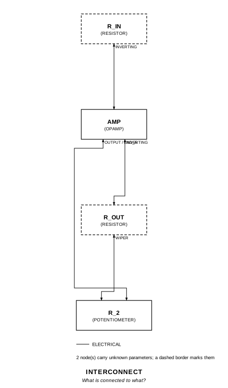
The interconnect view is fang’s own projection. It names the parts as the program does, so it reads against the code below.
What the program says
Section titled “What the program says”The page gives only the range, so the program derives the gain (t_network).
With R_a the part of R_2 between output and wiper and R_b the part below the
wiper, the wiper sits at -(R_O / R_I) E_I, and
E_O / E_I = -(R_O / R_I) (1 + R_a / R_b + R_a / R_O)With R_O = R_2 and the setting s counted from the output end, that is
-(1 / (1 - s) + s): -1 at s = 0, infinite at s = 1. setting records that
choice and holds the claim at s = 0.5, a gain of -2.5. The constraint writes
the formula out over the parts, and a second holds Z_in to R_I.
What the simulation found
Section titled “What the simulation found”out/simulation.txt, operating points:
| s | E_I | Gain | Claimed | Z_in |
|---|---|---|---|---|
| 0.5 | 1 V | -2.5 | -2.5 (a_v), holds | 10 kΩ, holds |
| 0 | 1 V | -1 | -1, holds | 10 kΩ, holds |
| 0.8 | 1 V | -5.8 | -5.8, holds | 10 kΩ, holds |
| 0.9 | 1 V | -10.9 | -10.9, holds | 10 kΩ, holds |
| 0.95 | 0.5 V | -20.95 | -20.95, holds | 10 kΩ, holds |
The wiper sits at -1 V for E_I = 1 V whatever the setting, and Z_in stays 10 kΩ. The bench stays off the infinite end, where any E_I saturates the output; at s = 0.95 the drive is halved to keep E_O inside the swing.
Running it
Section titled “Running it”fang check examples/ti_opamp_handbook/dc_amplifiers/inverting_gain_control/inverting_gain_control.pypython examples/regenerate.py ti_opamp_handbook/dc_amplifiers/inverting_gain_control # needs ngspiceThe whole program
Section titled “The whole program”"""Inverting gain control, SBOA092B page 73.Show 22 more lines
E_O = (-1 to infinity) E_I, Z_in = 10 kOhm
An inverting amplifier with a T network in the feedback: R_O runs from thesumming point to the wiper of R_2, a 10 kOhm pot from the output to ground.The page gives only the range. With R_a the part of R_2 between the outputand the wiper and R_b the part between the wiper and ground, the summingpoint is at ground, so the wiper sits at -(R_O / R_I) E_I, and the currentthat holds it there comes from the output through R_a:
E_O / E_I = -(R_O / R_I) (1 + R_a / R_b + R_a / R_O)
With the wiper at the output R_a is 0 and the gain is -1; as it nears groundR_b goes to 0 and the gain to infinity. With R_O = R_2 and the setting scounted from the output end, R_a = s R_2 and R_b = (1 - s) R_2, and the gainis -(1 / (1 - s) + s). The gain is not linear in the setting, which the pagedoes not say.
The program chose where the setting counts from and where the claim is held(`setting`). The bench checks four settings and stays off the infinite end,where any E_I saturates the output."""
import sysfrom decimal import Decimalfrom pathlib import Path
# The handbook's shared parts and bench live in the folder above the sections.sys.path.insert(0, str(Path(__file__).resolve().parents[2]))
from fang.lang import Parameter, System, kOhm, requirefrom fang.parts import Resistorfrom fang.rationale import Calculates, Chooses, Citesfrom fang.simulation import OperatingPoint
from handbook import ( Bench, Claim, Ground, OpAmp, Potentiometer, Run, Terminal, equals, minus, negative, over, product, ratio, total,)
class InvertingGainControl(System): """R_I into the summing point, R_O to the wiper of R_2, R_2 from output to ground."""
figure = Cites( "E_O = (-1 to infinity) E_I, Z_in = 10 kOhm. Convenient gain technique", document="SBOA092B, Handbook of Operational Amplifier Applications", locator="page 73, Inverting Gain Control", )
setting = Chooses( "Which end does R_2's setting count from, and where is the claim held?", selected=( "end 1 on the output and end 3 on ground, so the setting s is the " "fraction between the output and the wiper; the claim is held at " "s = 0.5, a gain of -2.5" ), alternatives=[ { "option": "hold the claim at one end of the range", "reason": ( "one end is -1, where R_2 does nothing, and the other is " "infinite; the middle is where the T network shows" ), }, ], rationale=("the figure gives R_2's value and no setting",), )
t_network = Calculates( "E_O / E_I = -(R_O / R_I) (1 + R_a / R_b + R_a / R_O)", inputs=("r_in", "r_out", "r_2"), result=( "-(1 / (1 - s) + s) with R_O = R_2: -1 at s = 0, -2.5 at 0.5, " "-5.8 at 0.8, -10.9 at 0.9, -20.95 at 0.95" ), )
a_v = Parameter("1", default=Decimal("-2.5") * ratio, description="E_O / E_I at the chosen setting") z_in = Parameter("Ohm", default=10 * kOhm, description="what E_I sees")
e_in = Terminal() e_out = Terminal() r_in = Resistor(resistance=10 * kOhm) r_out = Resistor(resistance=10 * kOhm) r_2 = Potentiometer(resistance=10 * kOhm, setting=Decimal("0.5") * ratio) amp = OpAmp() ground = Ground()
def architecture(self): self.e_in.probe >> self.r_in.p1 self.r_in.p2 >> self.amp.inverting.signal self.amp.inverting.signal >> self.r_out.p1 self.r_out.p2 >> self.r_2.wiper self.amp.output.signal >> self.r_2.end_a self.r_2.end_b >> self.ground.node self.amp.output.signal >> self.e_out.probe self.amp.non_inverting.signal >> self.ground.node
def constraints(self): r_a = product(self.r_2.setting, self.r_2.resistance) r_b = product(minus(1 * ratio, self.r_2.setting), self.r_2.resistance) require( equals( self.a_v, negative( product( over(self.r_out.resistance, self.r_in.resistance), total(1 * ratio, over(r_a, r_b), over(r_a, self.r_out.resistance)), ) ), ) ) # The summing point is a virtual ground whatever the T does. require(equals(self.z_in, self.r_in.resistance))
def _setting(s: float, drive: float, gain: float) -> Run: return Run( f"s_{int(round(s * 100)):03d}", OperatingPoint(), drive={"e_in": f"DC {drive:g}"}, settings={"r_2": {"setting": s}}, measure={ "gain": "v({e_out.1}) / v({e_in.1})", "z_in": "-v({e_in.1}) / i(vdrive_e_in)", }, claims=[ Claim("gain", gain, within=0.001, note=f"-(1 / (1 - {s:g}) + {s:g})"), Claim("z_in", "z_in", within=0.001, unit="Ohm"), ], )
BENCH = Bench( page=73, title="Inverting Gain Control", runs=[ Run( "chosen", OperatingPoint(), drive={"e_in": "DC 1"}, measure={ "gain": "v({e_out.1}) / v({e_in.1})", "z_in": "-v({e_in.1}) / i(vdrive_e_in)", "wiper": "v({r_2.2})", }, claims=[ Claim("gain", "a_v", within=0.001), Claim("z_in", "z_in", within=0.001, unit="Ohm"), Claim( "wiper", -1, within=0.001, unit="V", note="the wiper sits at -(R_O / R_I) E_I whatever the setting", ), ], ), _setting(0.0, 1.0, -1.0), _setting(0.8, 1.0, -5.8), _setting(0.9, 1.0, -10.9), _setting(0.95, 0.5, -20.95), ],)The files it writes
Section titled “The files it writes”The parts, then the nets and the pads on them.
GND1 Ground -R1 10 kOhm -R2 10 kOhm -RV1 Potentiometer -TP1 Terminal -TP2 Terminal -U1 OpAmp -Net-(GND1-Pad1) GND1.1 RV1.3 U1.IN+Net-(R1-Pad1) R1.1 TP1.1Net-(R1-Pad2) R1.2 R2.1 U1.IN-Net-(R2-Pad2) R2.2 RV1.2Net-(RV1-Pad1) RV1.1 TP2.1 U1.OUTEvery check that ran, and every one left undecided.
2 checks, 0 failed, 0 undecidedWhat the elaborated graph contains, by entity kind.
1 block 1 calculation 7 component 16 connection 2 constraint 1 decision 1 evidence 3 interface 13 pin 13 port 58 totalsnapshot sha256:fa7ec70fb421cb25fadc78a9a48aac4ca7f57eb1723125cadf61b835707b3e23All of it, including the KiCad netlist, is in
examples/ti_opamp_handbook/dc_amplifiers/inverting_gain_control/out/. Rebuild it with:
fang build examples/ti_opamp_handbook/dc_amplifiers/inverting_gain_control/inverting_gain_control.py