
Examples
Noninverting amp
An a.c.-coupled non-inverting amplifier, and the two numbers a textbook asks of it: "What is the input impedance in Figure 4.44? What is Av?" Zin = 68.75 kΩ, Av = 16: non-inverting, or +24 dB, over the midband.
The third example that is not a board. The two under
jee_advanced/ are exam questions with one right answer;
this one is here for what they do not show, which is that the answer depends
on a reading of the schematic before it depends on any arithmetic. The
reading is a decision, so it is an entity in the graph rather than a sentence
in a comment, and out/rationale.md carries it out with what it rejected.
The circuit
Section titled “The circuit”c_in | .1 µF | the source onto the + input |
r_bias_upper, r_series | 220 kΩ, 100 kΩ | + input → bias node, side by side |
r_bias_lower, c_bias | 220 kΩ, .5 µF | the bias node to ground, bypassed |
r_feedback, r_gain, c_gain | 30 kΩ, 2 kΩ, 1 µF | output → − input → ground |
c_out, r_load | .2 µF, 12 kΩ | the output into its load |
U1 is an ideal op amp: two analog inputs, one analog output, and no rails,
because the figure draws none. GND1 is a one-terminal part that marks the
node every claim is measured against.
Neither answer is a property of the resistors
Section titled “Neither answer is a property of the resistors”Both are midband answers, and which nodes are a.c. grounds is what decides them:
- The .5 µF holds the bias node at a.c. ground, so the 220 kΩ and the 100 kΩ both run from the input node to ground, in parallel 68.75 kΩ. The lower 220 kΩ never appears in the answer: the .5 µF is across it. The op amp’s own + input draws nothing worth subtracting.
- The 1 µF puts the bottom of the 2 kΩ at a.c. ground, which is what makes
the gain
1 + 30k/2krather than 1. At d.c. that capacitor is an open and the stage falls to unity gain, which is what keeps the output offset small. The 12 kΩ load does not enter it: the op amp’s output impedance is 0.
The reading
Section titled “The reading”The upper 220 kΩ is drawn over the top of the figure, and where its far end
lands is the whole question. reading records the one taken and both it
turned down:
reading = Chooses( "Where does the upper 220 k return to?", selected="to the bias node, beside the 100 k, ...", alternatives=[ {"reading": "to the op amp output, as a bootstrap", "reason": ...}, {"reading": "to a supply rail, making the two 220 k a divider", "reason": ...}, ],)Under the bootstrap reading the input impedance would be far higher than 68.75 kΩ, and under the divider reading the 100 kΩ would be the whole of it. Same drawing, three different answers, so the reading is recorded rather than assumed.
The program
Section titled “The program”noninverting_amp.py claims three numbers:
z_in = Parameter("Ohm", default=68.75 * kOhm, description="what the source sees ...")a_v = Parameter("1", default=16 * ratio, description="the midband voltage gain ...")midband = Parameter("Hz", default=1 * kHz, description="the bottom of the band ...")Two constraints check the answers against the parts:
require(equals(self.z_in, parallel(self.r_bias_upper.resistance, self.r_series.resistance)))require(equals(self.a_v, total(1 * ratio, over(self.r_feedback.resistance, self.r_gain.resistance))))and four more check what earns them: each capacitor’s reactance at the bottom of the claimed band, against the resistance it sits beside:
require(at_most(reactance(self.c_in.capacitance, self.midband), a_tenth_of(self.z_in)))reactance is 1 / (2πfC), written out as an expression tree. The reciprocal
of a frequency times a capacitance is an ohm, and Arithmetic checks that
where the expression is constructed, so a term with the wrong parameter in
it is rejected at the line that wrote it, not at the line that evaluated it.
At 1 kHz the four come out 1592 Ω against 6875, 318 Ω against 22 k, 159 Ω against 200, and 796 Ω against 1200. Six checks, none failed and none undecided. The gain leg is the tightest of the four, and that is not an accident: its corner is 79.6 Hz, the highest of
| R | C | corner | |
|---|---|---|---|
| input | 68.75 kΩ | .1 µF | 23.1 Hz |
| bias node | 220 kΩ | .5 µF | 1.4 Hz |
| gain leg | 2 kΩ | 1 µF | 79.6 Hz |
| output | 12 kΩ | .2 µF | 66.3 Hz |
so midband is a decade above it. Move any capacitor down a decade and the
two answers do not quietly stay true: a check fails and names which one.
Where the numbers came from
Section titled “Where the numbers came from”Neither claim was solved in the program (the kernel decides claims, it does
not solve circuits), and a claim about a band asks for a sweep rather than an
operating point. solve.py elaborates the same graph, has
fang.simulation compile an a.c. plan and lower it to SPICE, and runs ngspice
over 10 Hz to 1 MHz:
--- solved by ngspice-45.2, exit status 0 --- Av at 1 kHz 15.94 16 claimed Av at 10 kHz 16.00 Zin at 1 kHz 68,777 Ohm 68750 claimed Zin at 100 kHz 68,750 OhmBoth claimed numbers are limits: 68,750 Ω and 16 are what the circuit approaches once every capacitor is out of the way. At 1 kHz, the bottom edge the program claims, the gain is 0.4% short of 16 and the impedance 0.04% over 68.75 kΩ, both from the reactance still left in the network. A decade higher they are the claimed numbers.
Three parts carry no simulation model and are named as abstracted, which is
what lets the plan compile and what puts each one in the plan’s assumptions:
GND1 marks a node, TP1 marks a terminal, and U1 is an ideal op amp nobody
wrote a model for. Two cards are the script’s own and it says so: V1, the
source the figure implies and never draws, and E1, a controlled source with a
gain of a million standing in for the abstracted op amp. The analysis is still
the plan’s: the control block runs the .ac line lower_to_spice wrote rather
than asking for a second one.
What comes out
Section titled “What comes out”13 parts, 8 nets, 114 entities, 6 checks, none failed and none undecided.
out/noninverting_amp.net: the KiCad netlistout/noninverting_amp.kicad_sch: the KiCad schematic, andout/schematic.svgis KiCad’s own renderout/netlist.txt: the same projection as textout/checks.txt: six checks, all decidedout/graph.txt: 114 entities, by kindout/rationale.md: the question, the reading, the three calculations and the verification
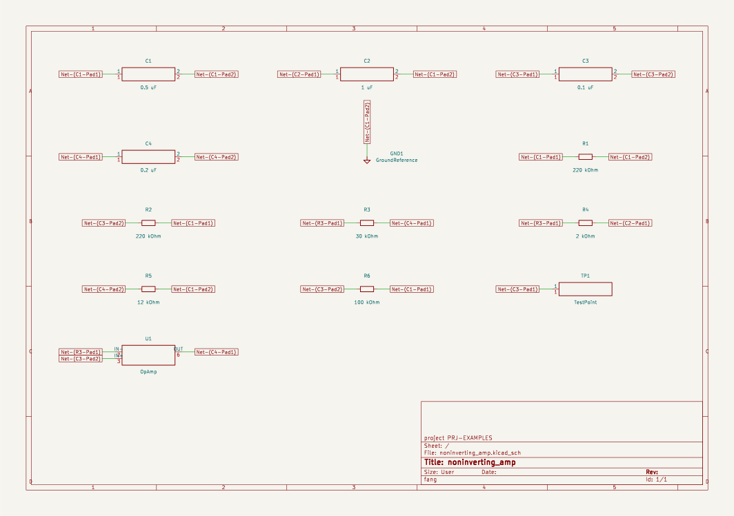
The resistors and the ground marker have drawn symbols; the op amp and the
four capacitors are boxes with their own pins on them, which is what the
schematic compiler does for a part nobody has a symbol for. U1’s pins come
out where an engineer expects them, IN- and IN+ on the left and OUT on
the right, because they are numbered 2, 3 and 6, the single-op-amp pinout, and
the box takes the pins in the order the graph gives them.
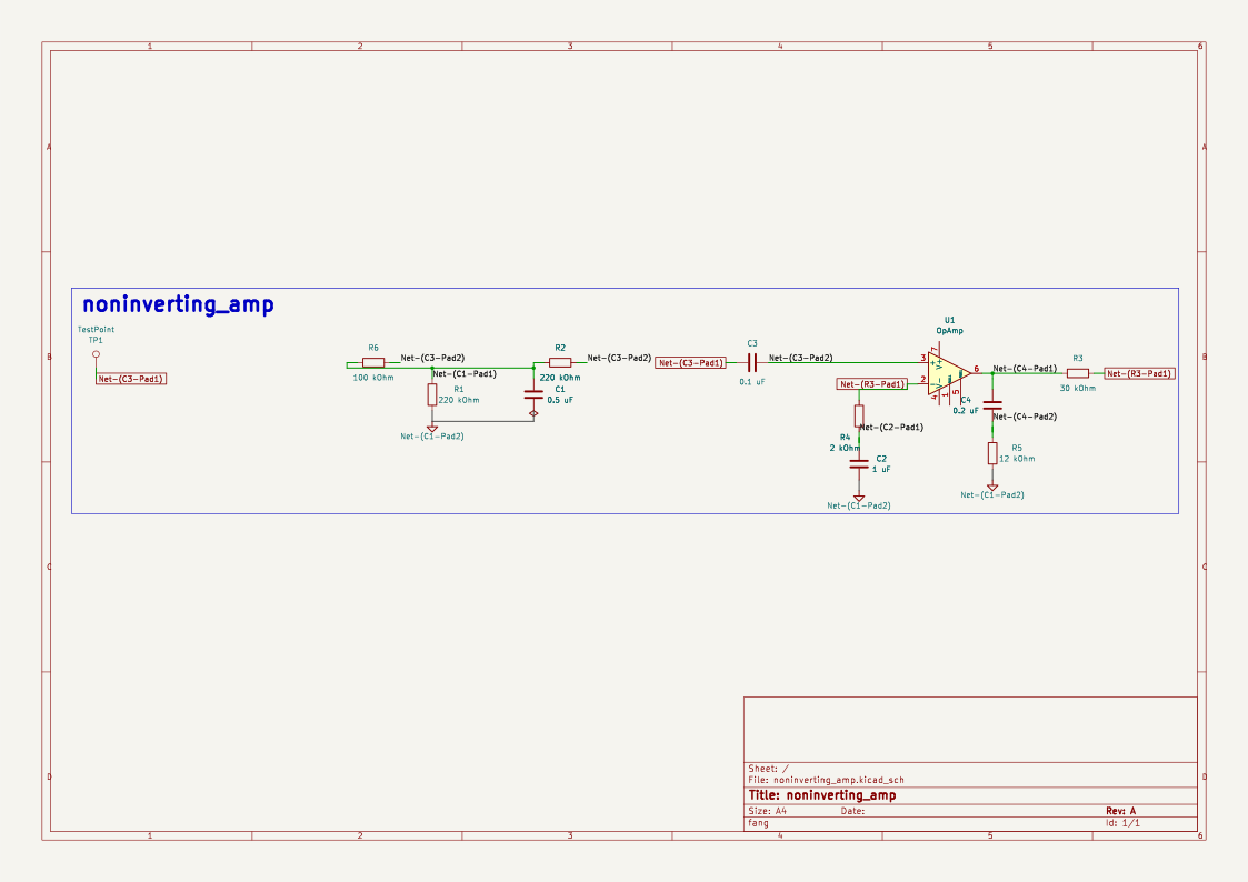
The same circuit is also drafted by copperhead, which places and wires parts
instead of laying them on a grid. Fang writes copperhead’s netlist intent,
out/copperhead/schematic.intent.json,
and copperhead draft schematic turns it into
out/copperhead/noninverting_amp.kicad_sch.
It draws with KiCad’s library symbols, so the op amp names one: symbol = "Amplifier_Operational:LM741", the standard single-op-amp drawing with pins 2,
3 and 6. That sets how the part is drawn, not which part it is. The ground
marker goes into the intent as KiCad’s ground symbol, power:GND, and its net
becomes a ground net: copperhead draws the ground symbol at each pin on it
rather than the marker as a part.
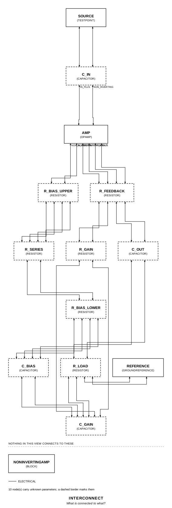
The interconnect view is fang’s own projection, and it names the parts the way
the program does, so r_bias_upper and r_series are visibly the two that
meet at the + input and leave together.
Running it
Section titled “Running it”fang check examples/noninverting_amp/noninverting_amp.pyfang netlist examples/noninverting_amp/noninverting_amp.pyfang view examples/noninverting_amp/noninverting_amp.py interconnect -o interconnect.svgfang schematic examples/noninverting_amp/noninverting_amp.py -o board.kicad_sch --svg board.svgfang schematic examples/noninverting_amp/noninverting_amp.py --drafter copperhead -o board.kicad_sch
python examples/noninverting_amp/solve.py # needs ngspice on PATHThe whole program
Section titled “The whole program”"""An a.c.-coupled non-inverting amplifier, and the two numbers asked of it.Show 32 more lines
The question is the one every textbook asks about this figure: "what is theinput impedance, and what is Av?" Both answers are midband answers, and thatis the whole of the problem -- neither number is a property of the resistorsalone. They are properties of which resistors return to an a.c. ground, andwhich nodes are a.c. grounds is set by the four capacitors.
The figure, node by node:
the input a .1 uF from the source onto the + input the bias 220 k from the + input back to a bias node, 100 k beside it, and at that node 220 k to ground with .5 uF across it the gain 30 k from the output to the - input, 2 k from there to ground through 1 uF the output .2 uF into a 12 k load
Like the two `jee_advanced` examples beside it, this is not a board. It ishere because the answer depends on a reading of the schematic, and a readingis a decision: `reading` below records which one was taken and what itrejected, so the two numbers can be read back to their premise instead ofbeing believed.
The claims are `z_in` and `a_v`. The four checks under them are what earnsthem: each capacitor's reactance at the bottom of the claimed band, againstthe resistance it sits beside. Move a capacitor by a decade and the answers donot quietly stay true -- a check fails and says which one.
Both claims are limits, and neither was solved here. `solve.py` beside thisfile lowers the graph to SPICE through `fang.simulation` and sweeps it inngspice, which is what a claim about a band asks for; the run agrees with bothnumbers and shows how fast they are approached."""
from fang.constraints import Arithmetic, Comparison, Literal, Nodefrom fang.interfaces import AnalogIn, AnalogOut, Pin, PinMapfrom fang.lang import ( Electrical, Parameter, ParameterRef, Part, System, UnitLiteral, kHz, kOhm, require, uF,)from fang.parts import Capacitor, Resistor, TestPointfrom fang.rationale import Calculates, Chooses, Cites, Requires, Verifies
#: A dimensionless literal, so a gain is a quantity like every other number.ratio = UnitLiteral("1")
#: Written out to the precision a Decimal keeps, because the constraints are#: evaluated in decimal and a binary float never reaches a quantity.TWO_PI = ratio("6.283185307179586")
# --------------------------------------------------------------------------# Writing the expression tree out# --------------------------------------------------------------------------## A parameter reference builds a node from one operator, and a node is not# itself an operand of Python's operators, so anything nested is written out.# That is not a workaround. Every node checks its own dimensions as it is# constructed, so 1 / (2*pi*f*C) is an impedance where it is written or it is# rejected there -- the reciprocal of a frequency times a capacitance is an# ohm, and nothing downstream has to re-check that.
def _node(value) -> Node: if isinstance(value, Node): return value if isinstance(value, ParameterRef): return value._node() return Literal.of(value)
def total(*terms) -> Arithmetic: """The sum of the terms named. Dimensions must agree.""" return Arithmetic("add", tuple(_node(term) for term in terms))
def product(*terms) -> Arithmetic: """The product of the terms named.""" return Arithmetic("mul", tuple(_node(term) for term in terms))
def over(numerator, denominator) -> Arithmetic: return Arithmetic("div", (_node(numerator), _node(denominator)))
def parallel(one, other) -> Arithmetic: """Two impedances side by side: the product over the sum.""" return over(product(one, other), total(one, other))
def reactance(capacitance, frequency) -> Arithmetic: """1 / (2*pi*f*C): what a capacitor is worth, in ohms, at one frequency.""" return over(1 * ratio, product(TWO_PI, frequency, capacitance))
def equals(left, right) -> Comparison: return Comparison("eq", (_node(left), _node(right)))
def at_most(left, right) -> Comparison: return Comparison("le", (_node(left), _node(right)))
def a_tenth_of(value) -> Arithmetic: """The margin that makes "a short" and "an open" worth saying.""" return over(value, 10 * ratio)
# --------------------------------------------------------------------------# The parts# --------------------------------------------------------------------------
class OpAmp(Part): """An ideal op amp: two analog inputs, one analog output, no rails.Show 7 more lines
The figure draws no supplies, so the part has none. The pin numbers are the single-op-amp 8-pin pinout an engineer expects -- 2, 3 and 6 -- and the package is the one a real part would arrive in, but nothing here claims a vendor: no part has been selected, and inventing one would be exactly the unearned certainty the kernel exists to prevent. """
designator_prefix = "U" # The standard single-op-amp drawing, whose pins are numbered 2, 3 and 6 as # these are. It says how the part is drawn, not which part it is: the # value stays OpAmp and no manufacturer is named. symbol = "Amplifier_Operational:LM741"
inverting = AnalogIn() non_inverting = AnalogIn() output = AnalogOut()
IN_MINUS = Pin("IN-", role="analog", number="2") IN_PLUS = Pin("IN+", role="analog", number="3") OUT = Pin("OUT", role="analog", number="6")
pinmap = PinMap( { "inverting.signal": "IN-", "non_inverting.signal": "IN+", "output.signal": "OUT", } )
class GroundReference(Part): """The node every claim below is measured against.Show 4 more lines
One terminal and no value: it marks a node rather than adding anything to it. """
designator_prefix = "GND"
node = Electrical() PIN1 = Pin("1", role="ground", number="1") pinmap = PinMap({"node.line": "1"})
class NonInvertingAmp(System): """The figure, then the two claims, then what makes them true."""
# -- the question, the reading it needed, and the answer ----------------
question = Cites( "What is the input impedance in Figure 4.44? What is Av?", document="problem set, question 40", locator="figure 4.44 -- the circuit as drawn, no frequency given", )
reading = Chooses( "Where does the upper 220 k return to?", selected=( "to the bias node, beside the 100 k, so both land on the + input " "at one end and on the .5 uF's node at the other" ), alternatives=[ { "reading": "to the op amp output, as a bootstrap", "reason": ( "the figure's top wire comes down to the left of the " "symbol, onto the + input, not to the output on its right" ), }, { "reading": "to a supply rail, making the two 220 k a divider", "reason": ( "no rail is drawn anywhere in the figure, and the lower " "220 k already returns the + input's bias current to " "ground on its own" ), }, ], rationale=( "under this reading both the 220 k and the 100 k run from the " "input node to a node the .5 uF holds at a.c. ground, which puts " "them in parallel across the input", "the answer is a reading of the drawing before it is arithmetic, " "so the reading is recorded rather than assumed", ), )
answer = Requires( "The input impedance is 68.75 kOhm and Av is 16, non-inverting", priority="MUST", validation="analysis", )
# -- the numbers behind it ----------------------------------------------
input_impedance = Calculates( "Zin = 220k || 100k, both returning to the a.c. ground the .5 uF makes", inputs=("r_bias_upper", "r_series", "c_bias"), result=( "68.75 kOhm. The lower 220 k does not appear: the .5 uF is across " "it, and the op amp's own + input draws nothing" ), requirements=("answer",), )
voltage_gain = Calculates( "Av = 1 + Rf/Rg, with the 1 uF shorting the 2 k leg to ground", inputs=("r_feedback", "r_gain", "c_gain"), result=( "1 + 30k/2k = 16, or +24 dB, non-inverting. At d.c. the 1 uF is an " "open and the stage falls to unity gain, which is what keeps the " "output offset small. The 12 k load does not enter it" ), requirements=("answer",), )
corner_frequencies = Calculates( "f = 1 / (2*pi*R*C), once per capacitor", inputs=("c_in", "c_bias", "c_gain", "c_out"), result=( "23.1 Hz at the input, 1.4 Hz at the bias node, 79.6 Hz at the " "gain leg, 66.3 Hz into the load. The 1 uF against 2 k is the " "highest of the four, so the midband both answers are claimed " "over starts about a decade above it" ), requirements=("answer",), )
answered = Verifies( "answer", method="analysis", evidence=("question",), result="PASS", )
# -- the claims, and the band they are claimed over ---------------------
z_in = Parameter( "Ohm", default=68.75 * kOhm, description="what the source sees, looking in through the .1 uF", ) a_v = Parameter( "1", default=16 * ratio, description="the midband voltage gain, output over input", ) midband = Parameter( "Hz", default=1 * kHz, description="the bottom of the band both answers are claimed over", )
# -- the figure ---------------------------------------------------------
source = TestPoint(package="TestPoint_Pad_D1.0mm") c_in = Capacitor(capacitance=0.1 * uF, package="C_0805")
# The two resistors that meet at the + input and leave together. Their far # end is the bias node, which the .5 uF holds at a.c. ground. r_bias_upper = Resistor(resistance=220 * kOhm, package="R_0805") r_series = Resistor(resistance=100 * kOhm, package="R_0805")
# The bias node itself: the d.c. return for the + input, bypassed. r_bias_lower = Resistor(resistance=220 * kOhm, package="R_0805") c_bias = Capacitor(capacitance=0.5 * uF, package="C_0805")
# The feedback network, and the leg that sets the gain above 1. r_feedback = Resistor(resistance=30 * kOhm, package="R_0805") r_gain = Resistor(resistance=2 * kOhm, package="R_0805") c_gain = Capacitor(capacitance=1 * uF, package="C_0805")
# The output, and what it drives. c_out = Capacitor(capacitance=0.2 * uF, package="C_0805") r_load = Resistor(resistance=12 * kOhm, package="R_0805")
amp = OpAmp(package="SOIC-8") reference = GroundReference(package="GND")
def architecture(self): # The input node: the coupling capacitor lands on the + input, and the # two bias resistors leave from there. self.source.probe >> self.c_in.p1 self.c_in.p2 >> self.amp.non_inverting.signal self.amp.non_inverting.signal >> self.r_bias_upper.p1 self.r_bias_upper.p1 >> self.r_series.p1
# The bias node: both of them arrive, the 220 k goes on to ground, and # the .5 uF is across it. self.r_bias_upper.p2 >> self.r_series.p2 self.r_series.p2 >> self.r_bias_lower.p1 self.r_bias_lower.p1 >> self.c_bias.p1
# The - input: the feedback resistor and the gain leg. self.amp.inverting.signal >> self.r_feedback.p1 self.r_feedback.p1 >> self.r_gain.p1 self.r_gain.p2 >> self.c_gain.p1
# The output node, and the load beyond the coupling capacitor. self.amp.output.signal >> self.r_feedback.p2 self.r_feedback.p2 >> self.c_out.p1 self.c_out.p2 >> self.r_load.p1
# Ground, and the reference every claim is measured against. self.r_bias_lower.p2 >> self.c_bias.p2 self.c_bias.p2 >> self.c_gain.p2 self.c_gain.p2 >> self.r_load.p2 self.r_load.p2 >> self.reference.node
def constraints(self): # The first answer. Both resistors run from the input node to a node # the .5 uF holds at a.c. ground, so they are in parallel across it, # and the op amp's own + input draws nothing worth subtracting. require( equals( self.z_in, parallel(self.r_bias_upper.resistance, self.r_series.resistance), ) )
# The second. The 1 uF puts the bottom of the 2 k on a.c. ground, which # is what makes the gain 1 + Rf/Rg rather than 1. require( equals( self.a_v, total( 1 * ratio, over(self.r_feedback.resistance, self.r_gain.resistance), ), ) )
# And what earns both: at the bottom of the claimed band, every # capacitor is worth at most a tenth of the resistance beside it, which # is what "treat it as a short" means when it is written down rather # than assumed. The gain leg is the tightest of the four. require( at_most( reactance(self.c_in.capacitance, self.midband), a_tenth_of(self.z_in), ) ) require( at_most( reactance(self.c_bias.capacitance, self.midband), a_tenth_of(self.r_bias_lower.resistance), ) ) require( at_most( reactance(self.c_gain.capacitance, self.midband), a_tenth_of(self.r_gain.resistance), ) ) require( at_most( reactance(self.c_out.capacitance, self.midband), a_tenth_of(self.r_load.resistance), ) )The files it writes
Section titled “The files it writes”The parts, then the nets and the pads on them.
C1 0.5 uF Package:C_0805C2 1 uF Package:C_0805C3 0.1 uF Package:C_0805C4 0.2 uF Package:C_0805GND1 GroundReference Package:GNDR1 220 kOhm Package:R_0805R2 220 kOhm Package:R_0805R3 30 kOhm Package:R_0805R4 2 kOhm Package:R_0805R5 12 kOhm Package:R_0805R6 100 kOhm Package:R_0805TP1 TestPoint Package:TestPoint_Pad_D1.0mmU1 OpAmp Package:SOIC-8Net-(C1-Pad1) C1.1 R1.1 R2.2 R6.2Net-(C1-Pad2) C1.2 C2.2 GND1.1 R1.2 R5.2Net-(C2-Pad1) C2.1 R4.2Net-(C3-Pad1) C3.1 TP1.1Net-(C3-Pad2) C3.2 R2.1 R6.1 U1.IN+Net-(C4-Pad1) C4.1 R3.2 U1.OUTNet-(C4-Pad2) C4.2 R5.1Net-(R3-Pad1) R3.1 R4.1 U1.IN-Every check that ran, and every one left undecided.
6 checks, 0 failed, 0 undecidedWhat the elaborated graph contains, by entity kind.
1 block 3 calculation 13 component 34 connection 6 constraint 1 decision 1 evidence 3 interface 25 pin 25 port 1 requirement 1 verification 114 totalsnapshot sha256:71c839dd1e08317242ec799984d00f9c773c76c896466cc6c0ffe4804a29173dAll of it, including the KiCad netlist, is in
examples/noninverting_amp/out/. Rebuild it with:
fang build examples/noninverting_amp/noninverting_amp.py