
Examples / TI op amp handbook / Current output
Meter amplifier
SBOA092B page 80, Meter Amplifier, "fully developed average reading meter": a follower whose feedback current runs through a bridge of two diodes and two 10 µF capacitors, with the meter across it.
Meter reading = 0.9 E_I / (R4 + R5) (E_I rms)The circuit
Section titled “The circuit”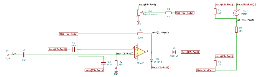
The schematic is drawn by copperhead’s
drafting engine from this circuit’s netlist, with KiCad’s own library symbols,
and it opens in KiCad as figure/meter_amplifier.kicad_sch.
The op amp is KiCad’s generic one, since the handbook’s are ideal, and each
terminal is a test point named as the program names it. KiCad reads back from
the sheet exactly the connections the circuit has; draw_figures.py refuses to write
one that does not.
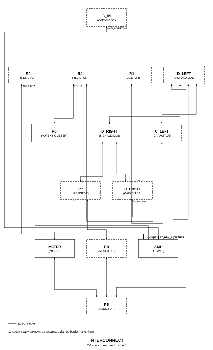
The interconnect view is fang’s own projection. It names the parts as the program does, so it reads against the code below.
What the program says
Section titled “What the program says”E_I comes in through a 1 µF capacitor onto the + input (220 kΩ to ground). The - input follows it, so E_I / (R4 + R5) flows through R4 (47 Ω) and the R5 rheostat to ground, and the output supplies it through the bridge. The output is the bridge’s top corner; one diode leads from it to the right corner and another from the left corner up to it; the capacitors join both corners to the bottom corner, which is the - input. R0 (220 kΩ) closes the loop at d.c. The meter, with R8 (68 kΩ) across it, sits between the right and left corners through R7 and R6.
The positive half of the current leaves through the right diode, the negative half comes back through the left one, and the capacitors pass both. What reaches the meter is the d.c. circulating through the two diodes in series, which is one diode’s average: half a cycle of the current. For a sine that is 0.45 E_I rms / (R4 + R5). The constraint says so:
require(equals(self.reading_per_volt, over(0.45, total(self.r4.resistance, in_circuit))))Decisions recorded: names (the figure labels two capacitors C1), movement
(a 100 Ω, 1 mA meter) and calibration (R5 at 53 Ω, so R4 + R5 = 100 Ω).
What the simulation found
Section titled “What the simulation found”out/simulation.txt, 100 mV rms at 1 kHz:
| Run | Meter average / E_I rms | Claimed |
|---|---|---|
sine, R4 + R5 = 100 Ω | 4.479 mA/V | 4.5 mA/V (reading_per_volt) ±1%, holds |
calibration, R4 + R5 = 147 Ω | 3.043 mA/V | 3.061 mA/V ±1%, holds |
The 0.5% shortfall is R0 and R8, which take a little of the current.
Where the handbook is off
Section titled “Where the handbook is off”The page prints 0.9 E_I / (R4 + R5), the full-wave average of a sine over its rms. The drawn bridge has two diodes and two capacitors, not four diodes, and its meter carries half that: 0.45 E_I / (R4 + R5), which is what ngspice measures. A four-diode bridge would read 0.9.
Running it
Section titled “Running it”fang check examples/ti_opamp_handbook/current_output/meter_amplifier/meter_amplifier.pypython examples/regenerate.py ti_opamp_handbook/current_output/meter_amplifier # needs ngspiceThe whole program
Section titled “The whole program”"""The meter amplifier, SBOA092B page 80: a fully developed average-reading meter.Show 25 more lines
Meter reading = 0.9 E_I / (R4 + R5) (E_I rms)
E_I comes in through C1 (1 uF) onto the + input, with R1 (220 kOhm) toground. The - input follows it, so the current through R4 and the R5rheostat to ground is E_I / (R4 + R5), and the output has to supply itthrough the bridge: the output drives the top corner, a diode leads fromthere to the right corner and another from the left corner up to it, the two10 uF capacitors join the left and right corners to the bottom corner, andthe bottom corner is the - input. R0 (220 kOhm) closes the loop at d.c.,which the capacitors cannot. The meter, with R8 (68 kOhm) across it, sitsbetween the right and left corners through R7 and R6 (100 Ohm each).
The positive half of the feedback current goes out through the right diodeand the negative half back through the left one, and the capacitors passboth. The meter carries the d.c. that circulates right corner, meter, leftcorner, left diode, right diode: what one diode carries on average, theaverage of one half-cycle of the current. For a sine that is 0.45 E_I rms /(R4 + R5), half of what the page prints. The program claims what the drawncircuit does and records the handbook's 0.9 in the citation.
The figure gives the meter no resistance and R5 no setting, and it names twodifferent capacitors C1; `movement`, `calibration` and `names` record whatwas taken."""
import sysfrom pathlib import Path
# The handbook's shared parts and bench live in the folder above the sections.sys.path.insert(0, str(Path(__file__).resolve().parents[2]))
from decimal import Decimal
from fang.lang import Ohm, Parameter, System, UnitLiteral, kOhm, require, uFfrom fang.parts import Capacitor, Resistorfrom fang.rationale import Chooses, Citesfrom fang.simulation import Transient
from handbook import ( Bench, Claim, Ground, Meter, OpAmp, Potentiometer, Run, SignalDiode, Terminal, equals, minus, over, product, ratio, total,)
#: The meter's average current per volt rms in.mA_per_V = UnitLiteral("mA/V")
class MeterAmplifier(System): """A follower whose feedback current runs through a two-diode, two-capacitor bridge."""
figure = Cites( "Meter reading = 0.9 E_I / (R4 + R5) (rms). R5: gain control " "(calibration). Fully developed average reading meter.", document="SBOA092B, Handbook of Operational Amplifier Applications", locator="page 80, Meter Amplifier", )
names = Chooses( "The figure labels two capacitors C1, one 1 uF and one 10 uF. Which is which?", selected=( "the 1 uF at the input is `c_in`; the two 10 uF in the bridge are " "`c_left` (drawn C1) and `c_right` (drawn C2)" ), alternatives=[ { "reading": "the input capacitor is 10 uF", "reason": "the value printed beside the input capacitor is 1 uF; " "only its name repeats", }, ], rationale=("the values are unambiguous where they are drawn; only the names collide",), )
movement = Chooses( "What is the meter's resistance?", selected="100 Ohm, a 1 mA movement", alternatives=[ { "option": "a 50 uA, 2 kOhm movement", "reason": "R8 (68 kOhm) across it would then take 3% of the " "current the meter should, where across 100 Ohm it takes 0.15%", }, ], rationale=( "the figure draws a meter and gives it no rating", "a 100 mV rms input into 100 Ohm puts the average near 0.45 mA, " "half of a 1 mA scale", ), )
calibration = Chooses( "Where is R5 set?", selected="0.47 of its travel, 53 Ohm in circuit, so R4 + R5 is 100 Ohm", alternatives=[ { "option": "the whole 100 Ohm", "reason": "used as a second run, to show the reading follows " "R4 + R5 as the calibration control moves", }, ], rationale=( "R5 is drawn as a rheostat: its wiper is tied to the end at R4, so " "what is in circuit is the part from the wiper to ground", "a round 100 Ohm makes the reading a round number", ), )
reading_per_volt = Parameter( "mA/V", default=Decimal("4.5") * mA_per_V, description="average meter current per volt rms of E_I: 0.45 / (R4 + R5)", )
e_in = Terminal() c_in = Capacitor(capacitance=1 * uF) r1 = Resistor(resistance=220 * kOhm) amp = OpAmp() ground = Ground()
r0 = Resistor(resistance=220 * kOhm) r4 = Resistor(resistance=47 * Ohm) r5 = Potentiometer(resistance=100 * Ohm, setting=Decimal("0.47") * ratio)
d_left = SignalDiode() d_right = SignalDiode() c_left = Capacitor(capacitance=10 * uF) c_right = Capacitor(capacitance=10 * uF) r6 = Resistor(resistance=100 * Ohm) r7 = Resistor(resistance=100 * Ohm) r8 = Resistor(resistance=68 * kOhm) meter = Meter(resistance=100 * Ohm)
def architecture(self): # The input: C1 onto the + input, R1 from there to ground. self.e_in.probe >> self.c_in.p1 self.c_in.p2 >> self.amp.non_inverting.signal self.amp.non_inverting.signal >> self.r1.p1 self.r1.p2 >> self.ground.node
# The - input: R0 from the output, R4 and the R5 rheostat to ground. self.amp.output.signal >> self.r0.p1 self.r0.p2 >> self.amp.inverting.signal self.amp.inverting.signal >> self.r4.p1 self.r4.p2 >> self.r5.end_a self.r5.end_a >> self.r5.wiper self.r5.end_b >> self.ground.node
# The bridge. The output is the top corner; the left diode points up # into it and the right diode down out of it. self.amp.output.signal >> self.d_left.p2 self.d_left.p2 >> self.d_right.p1 self.d_left.p1 >> self.c_left.p1 self.d_right.p2 >> self.c_right.p1 # The bottom corner is the - input. self.c_left.p2 >> self.c_right.p2 self.c_right.p2 >> self.amp.inverting.signal
# The meter, R8 across it, R6 and R7 to the left and right corners. self.d_left.p1 >> self.r6.p1 self.d_right.p2 >> self.r7.p1 self.r6.p2 >> self.r8.p1 self.r7.p2 >> self.r8.p2 self.r7.p2 >> self.meter.p1 self.meter.p2 >> self.r6.p2
def constraints(self): in_circuit = product(self.r5.resistance, minus(1 * ratio, self.r5.setting)) require( equals( self.reading_per_volt, over(Decimal("0.45") * ratio, total(self.r4.resistance, in_circuit)), ) )
#: The meter's average current over the input's rms, over whole periods.MEASURE = { "i_avg": "avg i(vm1_sense) from=100m to=200m", "e_rms": "rms v({e_in.1}) from=100m to=200m", "reading_per_volt": "i_avg / e_rms",}
HALF = ( "The handbook prints 0.9 E_I / (R4 + R5), the full-wave average of a sine " "over its rms. The drawn bridge has two diodes and two capacitors, and its " "meter carries one diode's average: 0.45. The 1% allowance covers R0 and R8, " "which between them take 0.5% of the current.")
BENCH = Bench( page=80, title="Meter Amplifier", runs=[ Run( "sine", Transient(stop="200m", step="2u"), drive={"e_in": "SIN(0 0.141421356 1k)"}, measure=MEASURE, claims=[Claim("reading_per_volt", "reading_per_volt", within=0.01, unit="A/V", note=HALF)], units={"i_avg": "A", "e_rms": "V"}, note="100 mV rms at 1 kHz. The first 100 ms let the 10 uF bridge " "capacitors reach their level; the next 100 are averaged.", ), Run( "calibration", Transient(stop="200m", step="2u"), drive={"e_in": "SIN(0 0.141421356 1k)"}, settings={"r5": {"setting": 0}}, measure=MEASURE, claims=[Claim("reading_per_volt", 0.45 / 147, within=0.01, unit="A/V", note="0.45 / (47 + 100) Ohm, with the whole of R5 in circuit")], units={"i_avg": "A", "e_rms": "V"}, note="R5 turned to its full 100 Ohm: the reading follows R4 + R5.", ), ],)The files it writes
Section titled “The files it writes”The parts, then the nets and the pads on them.
C1 1 uF -C2 10 uF -C3 10 uF -D1 SignalDiode -D2 SignalDiode -GND1 Ground -M1 Meter -R1 220 kOhm -R2 220 kOhm -R3 47 Ohm -R4 100 Ohm -R5 100 Ohm -R6 68 kOhm -RV1 Potentiometer -TP1 Terminal -U1 OpAmp -Net-(C1-Pad1) C1.1 TP1.1Net-(C1-Pad2) C1.2 R2.1 U1.IN+Net-(C2-Pad1) C2.1 D1.A R4.1Net-(C2-Pad2) C2.2 C3.2 R1.2 R3.1 U1.IN-Show 6 more lines
Net-(C3-Pad1) C3.1 D2.K R5.1Net-(D1-PadK) D1.K D2.A R1.1 U1.OUTNet-(GND1-Pad1) GND1.1 R2.2 RV1.3Net-(M1-Pad1) M1.1 R5.2 R6.2Net-(M1-Pad2) M1.2 R4.2 R6.1Net-(R3-Pad2) R3.2 RV1.1 RV1.2Every check that ran, and every one left undecided.
1 checks, 0 failed, 0 undecidedWhat the elaborated graph contains, by entity kind.
1 block 16 component 44 connection 1 constraint 3 decision 1 evidence 3 interface 32 pin 32 port 133 totalsnapshot sha256:e7303b8c6d06066da08676b15d67bccb4c1cac79da6c5cb799190d5c54c13b36All of it, including the KiCad netlist, is in
examples/ti_opamp_handbook/current_output/meter_amplifier/out/. Rebuild it with:
fang build examples/ti_opamp_handbook/current_output/meter_amplifier/meter_amplifier.py