
Examples / TI op amp handbook / Additional circuits
Absolute value
SBOA092B page 87, Absolute Value: two 10 kΩ resistors, two diodes and one op amp, a follower for +EI and an inverter for -EI.
E_O = |E_I|The circuit
Section titled “The circuit”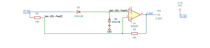
The schematic is drawn by copperhead’s
drafting engine from this circuit’s netlist, with KiCad’s own library symbols,
and it opens in KiCad as figure/absolute_value.kicad_sch.
The op amp is KiCad’s generic one, since the handbook’s are ideal, and each
terminal is a test point named as the program names it. KiCad reads back from
the sheet exactly the connections the circuit has; draw_figures.py refuses to write
one that does not.
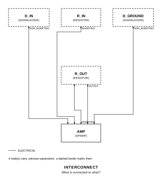
The interconnect view is fang’s own projection. It names the parts as the program does, so it reads against the code below.
What the program says
Section titled “What the program says”With R in and R across, the output is 2 V+ - E_I. Both diodes have their
cathodes on the + input, one anode on E_I and one on ground, so the + input
takes the higher of E_I and 0: E_I when it is positive (the output is E_I,
a_follow = 1), ground when it is negative (the output is -E_I,
a_invert = -1).
Where the handbook is off
Section titled “Where the handbook is off”The figure as printed puts E_I, both cathodes and the - input on one node and
the + input on ground. That leaves the left resistor and the upper diode in a
closed loop of their own and the - input held at E_I, and the op amp
saturates. The program records the wiring it simulates as a decision
(reading): every part the figure draws, both diodes in their drawn
orientation, with E_I on the upper diode’s anode and the left resistor and
the cathodes’ node on the + input. Reversing both diodes then gives
-|E_I|, as the page’s last sentence says.
What the simulation found
Section titled “What the simulation found”| Run | Measured | Claimed |
|---|---|---|
transfer, E_I = -5 V | 4.937 V | 5 V ± 0.1 V, holds |
transfer, E_I = -1 V | 0.937 V | 1 V ± 0.1 V, holds |
transfer, E_I = 0 | 0 V | 0 V ± 0.1 V, holds |
transfer, E_I = +1 V | 0.937 V | 1 V ± 0.1 V, holds |
transfer, E_I = +5 V | 4.937 V | 5 V ± 0.1 V, holds |
transfer, E_O / E_I at ±5 V | 0.987, -0.987 | 1, -1 (a_follow, a_invert) ± 2%, holds |
sine, 2 V at 100 Hz, both half-cycle peaks | 1.936 V | 2 V ± 0.1 V, holds |
This is not a precision circuit. The diodes are outside the loop and the output is about 63 mV short of |E_I|. It is not a full forward drop: the
- input draws nothing, so each diode carries only its partner’s leakage and sits at about 31 mV, and the output counts that twice. The + input is a node only leakage drives, so it lags a fast signal: at 1 kHz the same sine peaked near 1.89 V. A real op amp’s input bias current, which the model does not have, would move that node by more than the leakage does.
Running it
Section titled “Running it”fang check examples/ti_opamp_handbook/additional/absolute_value/absolute_value.pypython examples/regenerate.py ti_opamp_handbook/additional/absolute_value # needs ngspiceThe whole program
Section titled “The whole program”"""The absolute value circuit, SBOA092B page 87.Show 28 more lines
+E_I follower circuit -E_I inverter circuit E_O = |E_I|
Two equal resistors make the op amp an inverter of E_I, and two diodesdecide what the + input sees. The stage's output is 2 V+ - E_I: with the+ input at E_I it is E_I (the "follower"), with the + input at ground it is-E_I (the "inverter"). The diodes both have their cathodes on the + input,one with its anode on E_I and the other on ground, so the + input takeswhichever of E_I and 0 is higher: E_I when it is positive, 0 when it isnegative. The output is |E_I|.
The figure as printed does not wire it that way. It lands the source, thetwo cathodes and the - input on one node and the + input on ground, whichleaves the left resistor and the upper diode in a closed loop of their ownand holds the - input at E_I with nothing for the output to control.`reading` records the circuit simulated here: the diodes and resistors thefigure draws, with their orientations, with the source on the upper diode'sanode and the left resistor, and the cathodes' node on the + input.
Neither diode carries more than the other's leakage, because the + inputdraws nothing, so the error is not a full forward drop. It is the drop at afew nanoamps, about 30 mV, and the output carries it twice. It is not aprecision circuit: the diodes are outside the loop, and a real op amp'sinput bias current, which the model here does not have, would move the+ input by more than that."""
import sysfrom pathlib import Path
# The handbook's shared parts and bench live in the folder above the sections.sys.path.insert(0, str(Path(__file__).resolve().parents[2]))
from fang.lang import Parameter, System, kOhm, requirefrom fang.parts import Resistorfrom fang.rationale import Chooses, Citesfrom fang.simulation import DCSweep, Transient
from handbook import ( Bench, Claim, Ground, OpAmp, Run, SignalDiode, Terminal, equals, minus, negative, over, ratio, total,)
class AbsoluteValue(System): """E_I through R into the summing point, R back; the + input picks E_I or ground through two diodes."""
figure = Cites( "+E_I follower circuit, -E_I inverter circuit, E_O = |E_I|; full wave " "rectification. Reverse diodes to give E_O = -|E_I|", document="SBOA092B, Handbook of Operational Amplifier Applications", locator="page 87, Absolute Value", )
reading = Chooses( "The figure puts E_I, both cathodes and the - input on one node. How is it wired?", selected=( "E_I on the upper diode's anode and the left R; both cathodes on the " "+ input; the lower diode's anode on ground; the - input between the two Rs" ), alternatives=[ { "reading": "as printed", "reason": ( "the left R and the upper diode close on themselves, the - input " "is held at E_I by the source and the + input at ground, and the " "output has nothing to control; it saturates" ), }, { "reading": "as printed, less the wire from E_I to the - input", "reason": ( "the upper diode then passes only negative E_I into the inverter " "and the lower diode shorts the source there: a half-wave " "rectifier, not |E_I|" ), }, ], rationale=( "it keeps every part the figure draws, and the orientation of both diodes", "it is a follower for +E_I and an inverter for -E_I, as the page says", "reversing both diodes makes the + input take the lower of E_I and 0, " "which gives -|E_I|, the page's last sentence", ), )
a_follow = Parameter("1", default=1 * ratio, description="E_O / E_I for positive E_I, 2 - R/R") a_invert = Parameter("1", default=-1 * ratio, description="E_O / E_I for negative E_I, -R/R")
e_in = Terminal() e_out = Terminal() r_in = Resistor(resistance=10 * kOhm) r_out = Resistor(resistance=10 * kOhm) d_in = SignalDiode() d_ground = SignalDiode() amp = OpAmp() ground = Ground()
def architecture(self): self.e_in.probe >> self.r_in.p1 self.e_in.probe >> self.d_in.p1 self.d_in.p2 >> self.amp.non_inverting.signal self.d_ground.p2 >> self.amp.non_inverting.signal self.d_ground.p1 >> self.ground.node self.r_in.p2 >> self.amp.inverting.signal self.amp.inverting.signal >> self.r_out.p1 self.r_out.p2 >> self.amp.output.signal self.amp.output.signal >> self.e_out.probe
def constraints(self): gain = over(self.r_out.resistance, self.r_in.resistance) # + input at E_I: E_I (1 + R/R) - E_I (R/R). require(equals(self.a_follow, minus(total(1 * ratio, gain), gain))) # + input at ground: the inverting amplifier. require(equals(self.a_invert, negative(gain)))
BENCH = Bench( page=87, title="Absolute Value", runs=[ Run( "transfer", DCSweep(source="VDRIVE_e_in", start="-6", stop="6", step="0.01"), drive={"e_in": "DC 0"}, measure={ "out_n5": "find v({e_out.1}) at=-5", "out_n1": "find v({e_out.1}) at=-1", "out_0": "find v({e_out.1}) at=0", "out_p1": "find v({e_out.1}) at=1", "out_p5": "find v({e_out.1}) at=5", "vplus_p5": "find v({amp.IN+}) at=5", "gain_p5": "out_p5 / 5", "gain_n5": "out_n5 / -5", "vplus_n5": "find v({amp.IN+}) at=-5", }, claims=[ Claim("out_n5", 5, within=0.1, absolute=True, unit="V", note="-5 V in, inverted"), Claim("out_n1", 1, within=0.1, absolute=True, unit="V"), Claim("out_0", 0, within=0.1, absolute=True, unit="V"), Claim("out_p1", 1, within=0.1, absolute=True, unit="V"), Claim( "out_p5", 5, within=0.1, absolute=True, unit="V", note="+5 V in, followed. Each point is held to 0.1 V, not 0.1%: see the run's note", ), Claim( "gain_p5", "a_follow", within=0.02, note="E_O / E_I at +5 V: the follower, 1.3% low for the 63 mV", ), Claim("gain_n5", "a_invert", within=0.02, note="E_O / E_I at -5 V: the inverter"), ], units={"vplus_p5": "V", "vplus_n5": "V"}, note=( "E_I swept from -5 V to +5 V. The output is |E_I| less about " "60 mV: each diode sits at the drop it has at its partner's " "leakage, and the output is 2 V+ - E_I, so the error appears " "twice." ), ), Run( "sine", Transient(stop="30m", step="10u"), drive={"e_in": "SIN(0 2 100)"}, measure={ "peak_pos": "max v({e_out.1}) from=0 to=5m", "peak_neg": "max v({e_out.1}) from=5m to=10m", "lowest": "min v({e_out.1}) from=0 to=30m", }, claims=[ Claim("peak_pos", 2, within=0.1, absolute=True, unit="V", note="the positive half, followed"), Claim("peak_neg", 2, within=0.1, absolute=True, unit="V", note="the negative half, inverted: full wave"), ], units={"lowest": "V"}, note=( "A 2 V, 100 Hz sine: both halves come out positive, each peaking " "near 2 V. The + input is a node that only leakage drives, so it " "lags a fast signal: at 1 kHz the same peaks come out near 1.89 V." ), ), ],)The files it writes
Section titled “The files it writes”The parts, then the nets and the pads on them.
D1 SignalDiode -D2 SignalDiode -GND1 Ground -R1 10 kOhm -R2 10 kOhm -TP1 Terminal -TP2 Terminal -U1 OpAmp -Net-(D1-PadA) D1.A GND1.1Net-(D1-PadK) D1.K D2.K U1.IN+Net-(D2-PadA) D2.A R1.1 TP1.1Net-(R1-Pad2) R1.2 R2.1 U1.IN-Net-(R2-Pad2) R2.2 TP2.1 U1.OUTEvery check that ran, and every one left undecided.
2 checks, 0 failed, 0 undecidedWhat the elaborated graph contains, by entity kind.
1 block 8 component 18 connection 2 constraint 1 decision 1 evidence 3 interface 14 pin 14 port 62 totalsnapshot sha256:32b1540bb6c6d4b7690b850b8e6766be976dae3f0eb9f44dc6b9e2b7f17798f1All of it, including the KiCad netlist, is in
examples/ti_opamp_handbook/additional/absolute_value/out/. Rebuild it with:
fang build examples/ti_opamp_handbook/additional/absolute_value/absolute_value.py