
Examples / TI op amp handbook / Comparators
Clamped comparator
SBOA092B page 47, Figure 54, Fully Clamped Voltage Comparator: EI through R1 (100 kΩ) and a -15 V reference through R2 (1 MΩ) into the inverting input; CR1 (1N4148) from there to the tap of Ra/Rb (15 kΩ / 10 kΩ, from +15 V to the output); CR2 from the tap of Rb'/Ra' (3 kΩ / 15 kΩ, from the output to -15 V) back to it.
Threshold = -(R_2 / R_1) V_ref = 1.5 V (as printed)Negative clamping level = -(+V_sup) R_b / R_a = -10 VPositive clamping level = -(-V_sup) R_b' / R_a' = +3 VThe circuit
Section titled “The circuit”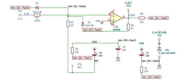
The schematic is drawn by copperhead’s
drafting engine from this circuit’s netlist, with KiCad’s own library symbols,
and it opens in KiCad as figure/clamped_comparator.kicad_sch.
The op amp is KiCad’s generic one, since the handbook’s are ideal, and each
terminal is a test point named as the program names it. KiCad reads back from
the sheet exactly the connections the circuit has; draw_figures.py refuses to write
one that does not.
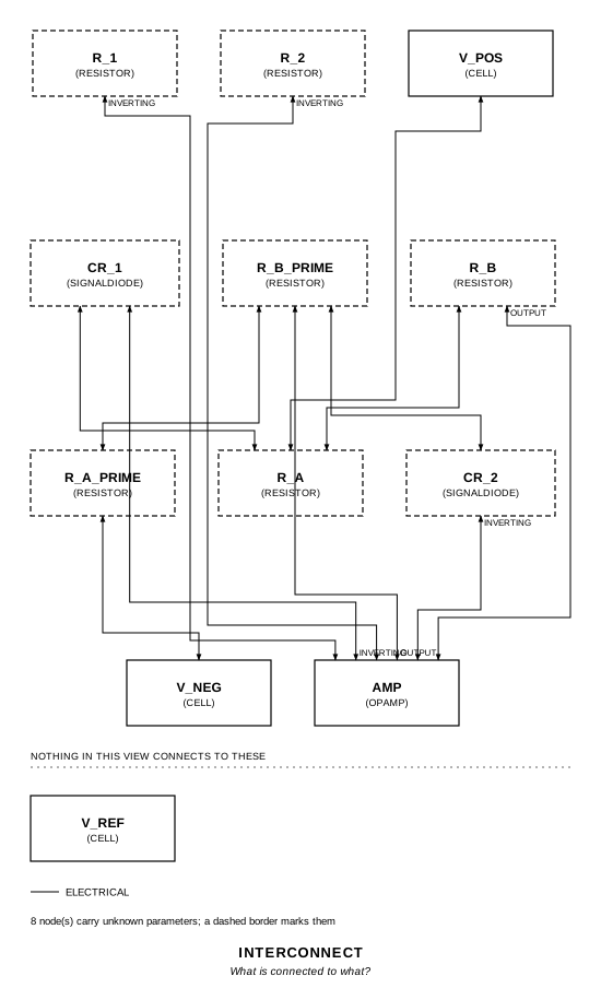
The interconnect view is fang’s own projection. It names the parts as the program does, so it reads against the code below.
What the program says
Section titled “What the program says”The printed numbers are parameters tied to the drawn parts: threshold
(1.5 V, from -(R_1 / R_2) V_ref), clamp_low_ideal (-10 V) and
clamp_high_ideal (+3 V). Those two assume the tap sits at ground when the
diode conducts. It actually sits one diode drop past the summing point, and
the diode’s current (15 µA at the two test inputs, 3 V and 0 V) also flows
in the divider:
E_O low = -(R_b / R_a)(V_sup + V_D) - V_D - R_b I_D = -10.807 VE_O high = +(R_b' / R_a')(V_sup + V_D) + V_D + R_b' I_D = +3.518 VThe drop is the one choice the program makes (diode_drop): 0.394 V, a
1N4148 model at 15 µA. clamp_low and clamp_high hold the two levels. The
three rails are cells.
What the simulation found
Section titled “What the simulation found”| Run | Measured | Claimed |
|---|---|---|
above_threshold (E_I = 3 V), CR_1 drop | 0.394 V | 0.394 V (v_diode), holds |
above_threshold, E_O | -10.81 V | -10.807 V (clamp_low), holds |
below_threshold (E_I = 0 V), CR_2 drop | 0.394 V | 0.394 V (v_diode), holds |
below_threshold, E_O | 3.518 V | 3.518 V (clamp_high), holds |
transfer, E_I where E_O crosses mid-swing | 1.500 V | 1.5 V (threshold), holds |
figure_waveform (2 V peak, 1 kHz), max E_O | 3.624 V | 3.624 V, holds |
figure_waveform, min E_O | -10.62 V | -10.62 V, holds |
In the transient the clamps move with the diode current: at the -2 V trough CR_2 carries 35 µA, at the +2 V crest CR_1 only 5 µA, and the same formula gives both numbers. The figure’s own trace sits near +3.7 V and -10.7 V.
Where the handbook is off
Section titled “Where the handbook is off”- The threshold formula is upside down. -(R_2 / R_1) V_ref is -(10)(-15 V) = 150 V. The threshold, where E_I / R_1 cancels V_ref / R_2, is -(R_1 / R_2) V_ref = 1.5 V, which is the number printed.
- The clamp levels leave out the diodes. ngspice clamps at -10.81 V and +3.52 V (at 15 µA of diode current), not -10 V and +3 V. The negative clamp moves 1.67 V per volt of diode drop and the positive 1.2 V per volt. The page’s own waveform agrees with the simulation, not the formulas.
Running it
Section titled “Running it”fang check examples/ti_opamp_handbook/comparators/clamped_comparator/clamped_comparator.pypython examples/regenerate.py ti_opamp_handbook/comparators/clamped_comparator # needs ngspiceThe whole program
Section titled “The whole program”"""The fully clamped voltage comparator, SBOA092B page 47 (Figure 54).Show 32 more lines
Threshold = -(R_2 / R_1) V_ref = -(1 MOhm / 100 kOhm)(-15 V) = 1.5 V (as printed) Negative clamping level = -(+V_sup) R_b / R_a = -10 V Positive clamping level = -(-V_sup) R_b' / R_a' = +3 V
An inverting summer whose feedback is two diodes into two dividers. E_I comesin through R_1 and the -15 V reference through R_2, so the summing pointcrosses zero where E_I / R_1 = 15 V / R_2, at 1.5 V. Above that the outputfalls until the divider R_a/R_b, strung from +15 V to the output, brings itstap below the summing point and CR_1 conducts; below it the output rises untilthe R_b'/R_a' tap, strung from the output to -15 V, rises above the summingpoint and CR_2 conducts. Either way the loop closes through a diode and holdsthe output there.
The printed threshold formula has the resistor ratio upside down:(R_2 / R_1) is 10, which with -15 V gives 150 V. The threshold is-(R_1 / R_2) V_ref = 1.5 V, which is the number the page prints.
The printed clamp levels are the dividers' outputs with each tap exactly atground, as if the diodes dropped nothing. The tap actually sits a diode dropbeyond the summing point, and the diode's current (the summing point's excess,15 uA at the two test inputs) also flows in the divider. So the output goesfurther than printed:
E_O low = -(R_b / R_a)(V_sup + V_D) - V_D - R_b I_D E_O high = +(R_b' / R_a')(V_sup + V_D) + V_D + R_b' I_D
The figure's own waveform shows it: it clamps near -10.7 V and +3.7 V, not-10 and +3. The diode drop is the one thing the program has to decide(`diode_drop`): a 1N4148 at 15 uA, which the bench's diode model puts at0.394 V. The bench measures it, and the two clamps, and the threshold."""
import sysfrom decimal import Decimalfrom pathlib import Path
# The handbook's shared parts and bench live in the folder above the sections.sys.path.insert(0, str(Path(__file__).resolve().parents[2]))
from fang.lang import A, MOhm, Parameter, System, V, kOhm, require, uAfrom fang.parts import Resistorfrom fang.rationale import Calculates, Chooses, Citesfrom fang.simulation import DCSweep, OperatingPoint, Transient
from handbook import ( Bench, Cell, Claim, Ground, OpAmp, Run, SignalDiode, Terminal, equals, minus, negative, over, product, ratio, total, within,)
class ClampedComparator(System): """An inverting summer whose feedback is a diode into each of two dividers."""
figure = Cites( "Threshold = -(R_2 / R_1) V_ref = -(1 MOhm / 100 kOhm)(-15 VDC) = 1.5 VDC; " "Negative clamping level = -(+V_sup) Rb / Ra = -15 VDC 10 kOhm / 15 kOhm = -10 VDC; " "Positive clamping level = -(-V_sup) Rb / Ra = +15 VDC 3 kOhm / 15 kOhm = +3 VDC; " "E_O = -10 VDC for E_I > 1.5 VDC; E_O = +3 VDC for E_I < 1.5 VDC", document="SBOA092B, Handbook of Operational Amplifier Applications", locator="page 47, Figure 54, Fully Clamped Voltage Comparator", )
diode_drop = Chooses( "What does each 1N4148 drop while it clamps?", selected=( "0.394 V: the 1N4148 model at the 15 uA the summing point sends " "through it for E_I = 3 V (CR_1) or 0 V (CR_2)" ), alternatives=[ { "option": "0 V, as the printed clamp formulas assume", "reason": ( "the output then clamps at -10 V and +3 V, which neither " "the simulation nor the figure's own waveform shows" ), }, { "option": "0.6 V, the usual rule of thumb", "reason": ( "that is a diode at around a milliamp; at 15 uA a 1N4148 " "drops about 0.4 V" ), }, ], rationale=( "the clamp level moves by 1.7 V per volt of drop on the negative side " "and 1.2 V per volt on the positive, so the drop is not negligible", "the drop is the model's at the current it actually carries", ), )
clamps = Calculates( "E_O = the divider's output with its tap one diode drop past the summing " "point, plus the diode's current through R_b", inputs=("r_a", "r_b", "r_b_prime", "r_a_prime", "cr_1", "cr_2"), result=( "-(10/15)(15.394) - 0.394 - 10 kOhm x 15 uA = -10.807 V, and " "(3/15)(15.394) + 0.394 + 3 kOhm x 15 uA = +3.518 V" ), )
# The printed claims, which the drawn circuit gives with ideal diodes. threshold = Parameter("V", default=Decimal("1.5") * V, description="where E_O switches") clamp_low_ideal = Parameter("V", default=-10 * V, description="the printed negative clamp") clamp_high_ideal = Parameter("V", default=3 * V, description="the printed positive clamp")
# What the circuit gives with a real diode drop. v_diode = Parameter("V", default=Decimal("0.394") * V, description="each diode's drop") e_test_high = Parameter("V", default=3 * V, description="the input the low clamp is read at") e_test_low = Parameter("V", default=0 * V, description="the input the high clamp is read at") i_diode = Parameter("A", default=15 * uA, description="the diode's current at either test input") clamp_low = Parameter("V", default=Decimal("-10.807") * V, description="E_O at E_I = 3 V") clamp_high = Parameter("V", default=Decimal("3.518") * V, description="E_O at E_I = 0 V")
e_in = Terminal() e_in_return = Terminal() ref = Terminal() e_out = Terminal() e_out_return = Terminal()
r_1 = Resistor(resistance=100 * kOhm) r_2 = Resistor(resistance=1 * MOhm) cr_1 = SignalDiode() cr_2 = SignalDiode() r_a = Resistor(resistance=15 * kOhm) r_b = Resistor(resistance=10 * kOhm) r_b_prime = Resistor(resistance=3 * kOhm) r_a_prime = Resistor(resistance=15 * kOhm) amp = OpAmp()
v_ref = Cell(voltage=15 * V) v_pos = Cell(voltage=15 * V) v_neg = Cell(voltage=15 * V) ground = Ground()
def architecture(self): # The summing point: E_I through R_1, the reference through R_2. self.e_in.probe >> self.r_1.p1 self.r_1.p2 >> self.amp.inverting.signal self.ref.probe >> self.r_2.p1 self.r_2.p2 >> self.amp.inverting.signal self.v_ref.p2 >> self.ref.probe # CR_1 from the summing point to the R_a/R_b tap, CR_2 from the # R_b'/R_a' tap back to it. self.amp.inverting.signal >> self.cr_1.p1 self.cr_1.p2 >> self.r_a.p2 self.r_a.p2 >> self.r_b.p1 self.r_b_prime.p2 >> self.cr_2.p1 self.cr_2.p2 >> self.amp.inverting.signal # The string: +15 V, R_a, R_b, the output, R_b', R_a', -15 V. self.v_pos.p1 >> self.r_a.p1 self.r_b.p2 >> self.amp.output.signal self.amp.output.signal >> self.r_b_prime.p1 self.r_b_prime.p2 >> self.r_a_prime.p1 self.r_a_prime.p2 >> self.v_neg.p2 self.amp.output.signal >> self.e_out.probe # Ground. self.amp.non_inverting.signal >> self.ground.node self.v_ref.p1 >> self.ground.node self.v_pos.p2 >> self.ground.node self.v_neg.p1 >> self.ground.node self.e_in_return.probe >> self.ground.node self.e_out_return.probe >> self.ground.node
def constraints(self): v_ref = negative(self.v_ref.voltage) # The threshold, with the ratio the right way up. require( equals( self.threshold, negative(product(over(self.r_1.resistance, self.r_2.resistance), v_ref)), ) ) # The printed clamps: each divider with its tap at ground. require( equals( self.clamp_low_ideal, negative(product(self.v_pos.voltage, over(self.r_b.resistance, self.r_a.resistance))), ) ) require( equals( self.clamp_high_ideal, product(self.v_neg.voltage, over(self.r_b_prime.resistance, self.r_a_prime.resistance)), ) ) # The diode's current: the summing point's excess, at each test input. require( equals( self.i_diode, total( over(self.e_test_high, self.r_1.resistance), over(v_ref, self.r_2.resistance), ), ) ) require( equals( self.i_diode, negative( total( over(self.e_test_low, self.r_1.resistance), over(v_ref, self.r_2.resistance), ) ), ) ) # The clamps with the drop and the current in. `within` takes its band # as a fraction of the target, so the negative one is written on # magnitudes. require( within( negative(self.clamp_low), total( product( over(self.r_b.resistance, self.r_a.resistance), total(self.v_pos.voltage, self.v_diode), ), self.v_diode, product(self.r_b.resistance, self.i_diode), ), 0.0001, ) ) require( within( self.clamp_high, total( product( over(self.r_b_prime.resistance, self.r_a_prime.resistance), total(self.v_neg.voltage, self.v_diode), ), self.v_diode, product(self.r_b_prime.resistance, self.i_diode), ), 0.0001, ) )
BENCH = Bench( page=47, title="Fully Clamped Voltage Comparator", runs=[ Run( "above_threshold", OperatingPoint(), drive={"e_in": "DC 3"}, measure={ "e_out": "v({e_out.1})", "v_cr1": "v({cr_1.A}) - v({cr_1.K})", }, claims=[ Claim( "v_cr1", "v_diode", within=0.01, unit="V", note="CR_1 carrying the summing point's 15 uA.", ), Claim( "e_out", "clamp_low", within=0.002, unit="V", note=( "The handbook prints -10 V (clamp_low_ideal); that is " "the clamp with a diode that drops nothing. With " "CR_1's 0.394 V and its 15 uA in R_b it is 0.8 V lower." ), ), ], ), Run( "below_threshold", OperatingPoint(), drive={"e_in": "DC 0"}, measure={ "e_out": "v({e_out.1})", "v_cr2": "v({cr_2.A}) - v({cr_2.K})", }, claims=[ Claim( "v_cr2", "v_diode", within=0.01, unit="V", note="CR_2 carrying the 15 uA the reference pulls out of the summing point.", ), Claim( "e_out", "clamp_high", within=0.002, unit="V", note=( "The handbook prints +3 V (clamp_high_ideal); with " "CR_2's drop and current it is 0.52 V higher." ), ), ], ), Run( "transfer", DCSweep(source="VDRIVE_e_in", start="-3", stop="5", step="1m"), drive={"e_in": "DC 0"}, measure={ "e_i_at_switch": "when v({e_out.1})=-3.645 fall=1", "e_out_at_1v": "find v({e_out.1}) at=1", "e_out_at_2v": "find v({e_out.1}) at=2", }, claims=[ Claim( "e_i_at_switch", "threshold", within=0.001, unit="V", note=( "Where the output crosses the middle of its two " "clamps. The handbook's -(R_2 / R_1) V_ref would be " "150 V; -(R_1 / R_2) V_ref is the 1.5 V it prints." ), ), ], units={"e_out_at_1v": "V", "e_out_at_2v": "V"}, note=( "E_I swept from -3 V to 5 V. Between the clamps the loop has " "no feedback, so the output crosses the whole 14 V within tens " "of microvolts of 1.5 V, what the open-loop gain needs." ), ), Run( "figure_waveform", Transient(stop="2m", step="0.5u"), drive={"e_in": "SIN(0 2 1k)"}, measure={ "e_out_min": "min v({e_out.1}) from=0 to=1m", "e_out_max": "max v({e_out.1}) from=0 to=1m", }, claims=[ Claim( "e_out_max", 3.624, within=0.005, unit="V", note=( "Not a handbook number. At the -2 V trough CR_2 " "carries 35 uA, not 15, and drops 0.432 V, so the " "same formula gives 3 + 1.2 x 0.432 + 3 kOhm x 35 uA " "= 3.624 V." ), ), Claim( "e_out_min", -10.62, within=0.005, unit="V", note=( "At the +2 V crest CR_1 carries only 5 uA and drops " "0.344 V: -10 - (25/15) x 0.344 - 10 kOhm x 5 uA = " "-10.62 V." ), ), ], note=( "The figure's own drive, a 2 V peak sine at 1 kHz. The " "figure's trace sits near +3.7 V and -10.7 V, well off the " "printed +3 V and -10 V." ), ), ],)The files it writes
Section titled “The files it writes”The parts, then the nets and the pads on them.
D1 SignalDiode -D2 SignalDiode -GND1 Ground -R1 100 kOhm -R2 1 MOhm -R3 15 kOhm -R4 15 kOhm -R5 10 kOhm -R6 3 kOhm -TP1 Terminal -TP2 Terminal -TP3 Terminal -TP4 Terminal -TP5 Terminal -U1 OpAmp -V1 15 V -V2 15 V -V3 15 V -Net-(D1-PadA) D1.A D2.K R1.2 R2.2 U1.IN-Net-(D1-PadK) D1.K R3.2 R5.1Show 7 more lines
Net-(D2-PadA) D2.A R4.1 R6.2Net-(GND1-Pad1) GND1.1 TP2.1 TP4.1 U1.IN+ V1.+ V2.- V3.+Net-(R1-Pad1) R1.1 TP1.1Net-(R2-Pad1) R2.1 TP5.1 V3.-Net-(R3-Pad1) R3.1 V2.+Net-(R4-Pad2) R4.2 V1.-Net-(R5-Pad2) R5.2 R6.1 TP3.1 U1.OUTEvery check that ran, and every one left undecided.
7 checks, 0 failed, 0 undecidedWhat the elaborated graph contains, by entity kind.
1 block 1 calculation 18 component 44 connection 7 constraint 1 decision 1 evidence 3 interface 31 pin 31 port 138 totalsnapshot sha256:61babec069b4eb318fd3a920c796d0225b9a5ae9bbfff65f6a742d69ee837319All of it, including the KiCad netlist, is in
examples/ti_opamp_handbook/comparators/clamped_comparator/out/. Rebuild it with:
fang build examples/ti_opamp_handbook/comparators/clamped_comparator/clamped_comparator.py