
Examples / TI op amp handbook / References
Constant current generator
SBOA092B page 51, Constant Current Generator: R1 (330 Ω) from +15 V to a 6 V zener, R2 (300 Ω) from the zener to the op amp's summing point, and the load RL from there to the output.
I = V_Z / R_2 = 6 / 300 = 20 mAR_1 = (15 - V_Z) / I_Z = 9 / 25 = 360 ΩR_L min = Saturation Voltage / I = 13.5 V / 20 mA = 675 ΩThe circuit
Section titled “The circuit”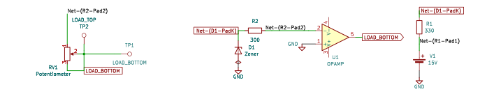
The schematic is drawn by copperhead’s
drafting engine from this circuit’s netlist, with KiCad’s own library symbols,
and it opens in KiCad as figure/constant_current_generator.kicad_sch.
The op amp is KiCad’s generic one, since the handbook’s are ideal, and each
terminal is a test point named as the program names it. KiCad reads back from
the sheet exactly the connections the circuit has; draw_figures.py refuses to write
one that does not.
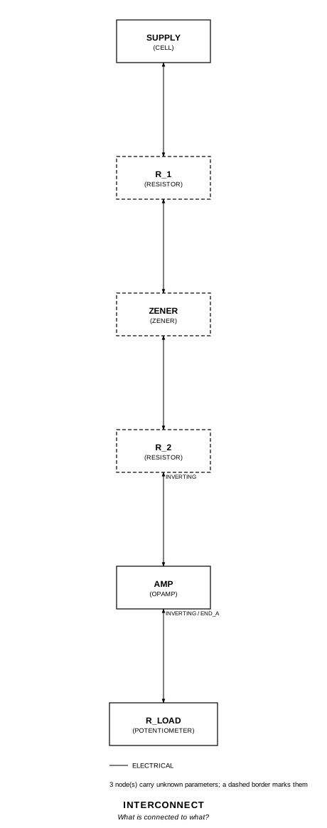
The interconnect view is fang’s own projection. It names the parts as the program does, so it reads against the code below.
What the program says
Section titled “What the program says”The loop holds the summing point at ground, so R_2 carries V_Z / R_2 into it
and all of that leaves through R_L to the output. The parameters: i_out
(20 mA, tied to the zener’s 6 V and R_2), i_zener (what the zener keeps,
(15 - V_Z) / R_1 - I = 7.27 mA), and r_load_max (13.5 V / I = 675 Ω), with
R_L required to be at most that.
Recorded choices: reading (which op amp input the R_2 / R_L node goes to),
bias (R_1 is the drawn 330 Ω, not the printed 360 Ω) and load (R_L is a
rheostat at 500 Ω, turned to 800 Ω for one run).
What the simulation found
Section titled “What the simulation found”| Run | Measured | Claimed |
|---|---|---|
inside_limit, I x R_2 / V_Z (measured) | 1 | 1 ± 0.01%, holds |
inside_limit, I | 20.09 mA | 20 mA (i_out) ± 1%, holds |
inside_limit, zener current | 7.096 mA | 7.273 mA (i_zener) ± 5%, holds |
inside_limit, V_Z | 6.028 V | not a claim |
past_limit (R_L = 800 Ω), E_O | -13.51 V | -13.5 V, holds |
past_limit, I / ((V_Z + 13.5 V) / (R_2 + R_L)) | 1 | 1 ± 0.1%, holds |
I is exactly V_Z / R_2 against the zener voltage the run measured. It is 0.5% above the nominal 20 mA because the zener model sits at 6.028 V at 7 mA, which is why that claim is held to 1%; a real 6 V zener is a 5% part.
Where the handbook is off
Section titled “Where the handbook is off”- The op amp’s inputs are swapped in the drawing. As drawn, the R_2 / R_L node goes to the + input and the - input to ground, so R_L feeds the output back positively. A transient of that wiring, run by hand, latches at +13.5 V. The program wires it the other way, the circuit the formulas describe, and records the reading.
- R_1’s formula leaves out I. R_2’s 20 mA comes out of the zener node, so R_1 carries I_Z + I, not I_Z. For I_Z = 25 mA it would be 9 / 45 = 200 Ω. The printed 360 Ω would leave the zener 5 mA; the drawn 330 Ω leaves it 7.3 mA (7.1 mA measured). 330 Ω is not a rounding of 360 Ω either; the program keeps the drawn value.
- “R_L min” is a maximum. The output sits at -I R_L, so 675 Ω is the largest load it can drive 20 mA through. At 800 Ω the output pins at -13.5 V, the summing point leaves ground, and I falls to (V_Z + 13.5 V) / (R_2 + R_L) = 17.8 mA.
Running it
Section titled “Running it”fang check examples/ti_opamp_handbook/references/constant_current_generator/constant_current_generator.pypython examples/regenerate.py ti_opamp_handbook/references/constant_current_generator # needs ngspiceThe whole program
Section titled “The whole program”"""The constant current generator, SBOA092B page 51.Show 33 more lines
I = V_Z / R_2 = 6 / 300 = 20 mA R_1 = (15 - V_Z) / I_Z = 9 / 25 = 360 Ohm R_L min = Saturation Voltage / I = 13.5 V / 20 mA = 675 Ohm
R_1 from +15 V biases a 6 V zener, and R_2 turns the zener's voltage into acurrent into the summing point, which the loop holds at ground. All of thatcurrent leaves through R_L to the output, whatever R_L is, so R_L is the loadand I is set by V_Z and R_2 alone.
Three things in the page do not hold up, and the program records each.
The figure has the op amp's inputs the wrong way round. As drawn, the node R_2and R_L share goes to the + input and the - input to ground, so R_L feeds theoutput back positively and the output latches at the rail (a transient of thedrawn wiring, run by hand, sits at +13.5 V). `reading` takes the inputs theother way, which is the circuit the page's formulas describe.
R_1's formula forgets that R_2's 20 mA comes out of the zener node too: R_1carries I_Z + I, not I_Z. With the drawn 330 Ohm, R_1 carries 27.3 mA and thezener keeps 7.3 mA, not 25 mA. The drawn 330 Ohm is not the printed 360 Ohmeither; neither is a rounding of the other, and 360 Ohm would leave the zener5 mA. `bias` keeps the drawn value.
And "R_L min" is a maximum. The output sits at -I R_L, so the largest load theoutput can drive 20 mA through before it saturates at -13.5 V is 675 Ohm.The bench runs R_L at 500 Ohm and then at 800 Ohm, past the limit, where theoutput pins at -13.5 V and the current falls to about 17.8 mA.
The current depends on the zener's actual voltage, and the model's is not6.000 V at 7.3 mA. The bench measures V_Z and checks I = V_Z / R_2 against themeasurement tightly, and against the nominal 20 mA to 1%."""
import sysfrom decimal import Decimalfrom pathlib import Path
# The handbook's shared parts and bench live in the folder above the sections.sys.path.insert(0, str(Path(__file__).resolve().parents[2]))
from fang.lang import Ohm, Parameter, System, V, mA, requirefrom fang.parts import Resistorfrom fang.rationale import Calculates, Chooses, Citesfrom fang.simulation import OperatingPoint
from handbook import ( Bench, Cell, Claim, Ground, OpAmp, Potentiometer, Run, Terminal, Zener, at_most, equals, minus, negative, over, ratio, within,)
class ConstantCurrentGenerator(System): """A zener's voltage across R_2 sets a current; the op amp forces it through R_L."""
figure = Cites( "Convenient current reference up to 20 mA: I = V_Z / R_2 = 6 / 300 = 20 mA; " "R_1 = (15 - V_Z) / I_Z = 9 / 25 = 360 Ohm; " "R_L min = Saturation Voltage / I = 13.5 V / 20 mA = 675 Ohm", document="SBOA092B, Handbook of Operational Amplifier Applications", locator="page 51, Constant Current Generator", )
reading = Chooses( "Which op amp input does the R_2 / R_L node go to?", selected="the - input, with the + input on ground", alternatives=[ { "option": "the + input, as drawn", "reason": ( "R_L then returns the output to the + input, positive " "feedback, and the output latches at +13.5 V; a transient " "of that wiring does exactly that" ), }, ], rationale=( "I = V_Z / R_2 needs the node held at ground, which only negative " "feedback does", "the drawing's + and - markings are swapped against every formula on the page", ), )
bias = Chooses( "Is R_1 330 Ohm, as drawn, or 360 Ohm, as printed?", selected="330 Ohm, as drawn", alternatives=[ { "option": "360 Ohm, the printed result", "reason": ( "it comes from (15 - V_Z) / I_Z, which leaves out the 20 mA " "R_2 takes from the same node; it would leave the zener " "5 mA, not 25 mA" ), }, ], rationale=( "the drawing is the circuit; the printed formula is wrong either way", "330 Ohm leaves the zener 7.3 mA, which keeps it in breakdown", ), )
load = Chooses( "What is R_L?", selected=( "a rheostat (a potentiometer with its wiper on one end) at 500 Ohm, " "turned to 800 Ohm for one run" ), alternatives=[ { "option": "a fixed resistor", "reason": "a run could not take the load past its limit", }, ], rationale=( "the figure gives R_L no value: it is whatever is being fed", "500 Ohm is inside the 675 Ohm limit, 800 Ohm is past it", ), )
zener_current = Calculates( "I_Z = (15 - V_Z) / R_1 - V_Z / R_2", inputs=("supply", "zener", "r_1", "r_2"), result=( "9 / 330 - 6 / 300 = 27.3 mA - 20 mA = 7.3 mA. The handbook's " "R_1 = (15 - V_Z) / I_Z drops the second term" ), )
i_out = Parameter("A", default=20 * mA, description="I, the current through R_L") i_zener = Parameter("A", default=Decimal("7.273") * mA, description="what the zener keeps") swing = Parameter("V", default=13.5 * V, description="how far the output can go") r_load_max = Parameter("Ohm", default=675 * Ohm, description="the handbook's 'R_L min'")
supply = Cell(voltage=15 * V) r_1 = Resistor(resistance=330 * Ohm) zener = Zener(reverse_voltage=6 * V) r_2 = Resistor(resistance=300 * Ohm) r_load = Potentiometer(resistance=500 * Ohm, setting=1 * ratio) amp = OpAmp() load_top = Terminal() load_bottom = Terminal() ground = Ground()
def architecture(self): # The zener node: R_1 from the rail, the zener to ground, R_2 onward. self.supply.p1 >> self.r_1.p1 self.r_1.p2 >> self.zener.p2 self.zener.p2 >> self.r_2.p1 # The summing point, and the load from it to the output. The figure's # two load terminals are joined by a wire; the current I flows there. self.r_2.p2 >> self.amp.inverting.signal self.amp.inverting.signal >> self.r_load.end_a self.r_load.wiper >> self.r_load.end_b self.r_load.end_b >> self.load_top.probe self.load_top.probe >> self.load_bottom.probe self.load_bottom.probe >> self.amp.output.signal # Ground. self.supply.p2 >> self.ground.node self.zener.p1 >> self.ground.node self.amp.non_inverting.signal >> self.ground.node
def constraints(self): require(equals(self.i_out, over(self.zener.reverse_voltage, self.r_2.resistance))) require( within( self.i_zener, minus( over(minus(self.supply.voltage, self.zener.reverse_voltage), self.r_1.resistance), self.i_out, ), 0.001, ) ) # The output stands at -I R_L, and cannot pass the swing. require(equals(self.swing, negative(self.amp.output_low))) require(equals(self.r_load_max, over(self.swing, self.i_out))) require(at_most(self.r_load.resistance, self.r_load_max))
BENCH = Bench( page=51, title="Constant Current Generator", runs=[ Run( "inside_limit", OperatingPoint(), measure={ "i_load": "(v({amp.IN-}) - v({amp.OUT})) / 500", "v_zener": "v({zener.K})", "i_over_vz_r2": "(v({amp.IN-}) - v({amp.OUT})) / 500 * 300 / v({zener.K})", "i_zener": "(15 - v({zener.K})) / 330 - (v({zener.K}) - v({amp.IN-})) / 300", "e_out": "v({amp.OUT})", }, claims=[ Claim( "i_over_vz_r2", 1.0, within=1e-4, note=( "I = V_Z / R_2 against the zener voltage the run " "measured: the op amp adds nothing to it." ), ), Claim( "i_load", "i_out", within=0.01, unit="A", note=( "Held to 1%, not 0.1%: the current is only as good " "as V_Z, and the zener model sits about 0.5% above " "6 V at 7.3 mA. A real 6 V zener is a 5% part." ), ), Claim( "i_zener", "i_zener", within=0.05, unit="A", note=( "Held to 5%: every 10 mV of V_Z moves it by 64 uA. " "The printed 25 mA is not what 330 Ohm gives." ), ), ], units={"v_zener": "V", "e_out": "V"}, ), Run( "past_limit", OperatingPoint(), settings={"r_load": {"resistance": 800}}, measure={ "i_load": "(v({amp.IN-}) - v({amp.OUT})) / 800", "e_out": "v({amp.OUT})", "i_over_divider": ( "(v({amp.IN-}) - v({amp.OUT})) / 800 * 1100 / (v({zener.K}) + 13.5)" ), }, claims=[ Claim( "e_out", -13.5, within=0.001, unit="V", note=( "Not a handbook claim: at 800 Ohm, past the 675 Ohm " "limit, the output is pinned at the -13.5 V swing. " "So 675 Ohm is the largest load, not the smallest." ), ), Claim( "i_over_divider", 1.0, within=1e-3, note=( "With the output pinned the loop is open, and the " "summing point is no longer at ground: R_2 and R_L " "are a plain divider from V_Z to -13.5 V, and I is " "(V_Z + 13.5 V) / (R_2 + R_L), about 17.8 mA." ), ), ], units={"e_out": "V", "i_load": "A"}, ), ],)The files it writes
Section titled “The files it writes”The parts, then the nets and the pads on them.
D1 Zener -GND1 Ground -R1 330 Ohm -R2 300 Ohm -RV1 Potentiometer -TP1 Terminal -TP2 Terminal -U1 OpAmp -V1 15 V -Net-(D1-PadA) D1.A GND1.1 U1.IN+ V1.-Net-(D1-PadK) D1.K R1.2 R2.1Net-(R1-Pad1) R1.1 V1.+Net-(R2-Pad2) R2.2 RV1.1 U1.IN-Net-(RV1-Pad2) RV1.2 RV1.3 TP1.1 TP2.1 U1.OUTEvery check that ran, and every one left undecided.
5 checks, 0 failed, 0 undecidedWhat the elaborated graph contains, by entity kind.
1 block 1 calculation 9 component 24 connection 5 constraint 3 decision 1 evidence 3 interface 17 pin 17 port 81 totalsnapshot sha256:a4e0a0da5548c4fa72ddeb903105d35c6fd4d44c19c0266879c7833196263074All of it, including the KiCad netlist, is in
examples/ti_opamp_handbook/references/constant_current_generator/out/. Rebuild it with:
fang build examples/ti_opamp_handbook/references/constant_current_generator/constant_current_generator.py