
Examples / TI op amp handbook / Lead and lag
Lag element
SBOA092B page 84, Lag Element: an inverting amplifier with CO across RO. The figure draws RI = 1 MΩ, RO = 10 kΩ and CO = 10 µF.
E_O = -(R_O / R_I) E_I / (1 + R_O C_O P) = -10 E_I / (10 + P)The circuit
Section titled “The circuit”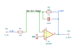
The schematic is drawn by copperhead’s
drafting engine from this circuit’s netlist, with KiCad’s own library symbols,
and it opens in KiCad as figure/lag_element.kicad_sch.
The op amp is KiCad’s generic one, since the handbook’s are ideal, and each
terminal is a test point named as the program names it. KiCad reads back from
the sheet exactly the connections the circuit has; draw_figures.py refuses to write
one that does not.
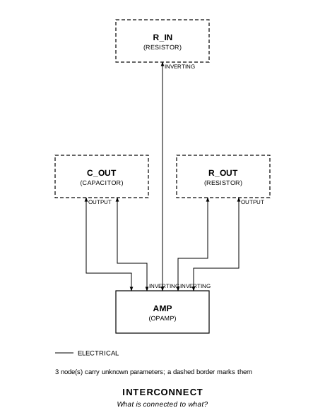
The interconnect view is fang’s own projection. It names the parts as the program does, so it reads against the code below.
What the program says
Section titled “What the program says”The claims are two parameters held to the parts: the DC gain
a_v = -R_O / R_I = -0.01, and the corner f_c = 1/(2π R_O C_O) = 1.59 Hz
(10 rad/s). The program keeps the drawn values and records that as a decision
(reading).
Where the handbook is off
Section titled “Where the handbook is off”The printed right-hand side, -10/(10 + P), has a DC gain of -1. The drawn values give -0.01/(1 + 0.1 P) = -0.1/(10 + P). The pole agrees (R_O C_O = 0.1 s); the gain is off by a factor of 100. R_I = 10 kΩ would make the printed form true. Swapping R_I and R_O does not: that gives -100/(1 + 10 P).
What the simulation found
Section titled “What the simulation found”out/simulation.txt, from the decks under
out/spice/:
| Run | Measured | Claimed |
|---|---|---|
dc_gain, operating point, E_I = 1 V | -0.01 | -0.01 (a_v), holds |
corner, gain at 10 mHz | 0.01 | 0.01, holds |
corner, -3 dB point | 1.592 Hz | 1.592 Hz (f_c), holds |
Running it
Section titled “Running it”fang check examples/ti_opamp_handbook/lead_lag/lag_element/lag_element.pypython examples/regenerate.py ti_opamp_handbook/lead_lag/lag_element # needs ngspiceThe whole program
Section titled “The whole program”"""The lag element, SBOA092B page 84.Show 16 more lines
E_O = -(R_O / R_I) E_I / (1 + R_O C_O P) = -10 E_I / (10 + P)
An inverting amplifier with C_O across R_O: a DC gain of -R_O/R_I and onepole where C_O's reactance equals R_O. The figure draws R_I = 1 MOhm,R_O = 10 kOhm and C_O = 10 uF.
The printed right-hand side does not follow from the drawn values.R_O C_O = 0.1 s, so the pole at 10 rad/s agrees, but -10/(10 + P) has a DCgain of -1, and R_O/R_I = 10k/1M = 0.01. The drawn circuit is-0.01/(1 + 0.1 P) = -0.1/(10 + P). The printed form is true for R_I = 10 kOhm(or R_I and R_O both 1 MOhm with C_O = 0.1 uF); no single swap of the drawnvalues gives it, since swapping R_I and R_O makes a gain of -100 and a poleat 0.1 rad/s. `reading` records that the program keeps the drawn values andclaims what they do: a gain of -0.01 and a corner at 1.59 Hz."""
import sysfrom decimal import Decimalfrom pathlib import Path
# The handbook's shared parts and bench live in the folder above the sections.sys.path.insert(0, str(Path(__file__).resolve().parents[2]))
from fang.lang import Hz, MOhm, Parameter, System, kOhm, require, uFfrom fang.parts import Capacitor, Resistorfrom fang.rationale import Chooses, Citesfrom fang.simulation import ACSweep, OperatingPoint
from handbook import ( Bench, Claim, Ground, OpAmp, Run, Terminal, corner, equals, negative, over, ratio, within,)
class LagElement(System): """E_I through R_I into the summing point, R_O and C_O side by side back from the output."""
figure = Cites( "E_O = -(R_O / R_I) E_I / (1 + R_O C_O P) = -10 E_I / (10 + P); " "integrating type phase lag", document="SBOA092B, Handbook of Operational Amplifier Applications", locator="page 84, Lag Element", )
reading = Chooses( "The drawn values give -0.01/(1 + 0.1 P); the page prints -10/(10 + P), a DC gain of -1. Which is simulated?", selected=( "the drawn values, R_I 1 MOhm, R_O 10 kOhm, C_O 10 uF: a DC gain " "of -0.01 and a corner at 10 rad/s, 1.59 Hz" ), alternatives=[ { "option": "R_I = 10 kOhm, which makes the printed -10/(10 + P) true", "reason": ( "it is the likeliest intent, but it changes a value the " "figure prints; the program simulates what is drawn and " "says where the formula parts from it" ), }, { "option": "R_I and R_O swapped", "reason": ( "1 MOhm across 10 uF is a 10 s time constant and a gain " "of -100: -100/(1 + 10 P), further from the printed form " "than the drawing is" ), }, ], rationale=( "R_O C_O = 0.1 s agrees with the printed pole at P = -10, so " "the lag is right and only the gain is off", "-10/(10 + P) needs R_O/R_I = 1; 10k/1M is 0.01", ), )
a_v = Parameter("1", default=-0.01 * ratio, description="E_O / E_I at DC") f_c = Parameter( "Hz", default=Decimal("1.59155") * Hz, description="the lag's corner, 1/(2 pi R_O C_O)" )
e_in = Terminal() e_out = Terminal() r_in = Resistor(resistance=1 * MOhm) r_out = Resistor(resistance=10 * kOhm) c_out = Capacitor(capacitance=10 * uF) amp = OpAmp() ground = Ground()
def architecture(self): self.e_in.probe >> self.r_in.p1 self.r_in.p2 >> self.amp.inverting.signal self.amp.inverting.signal >> self.r_out.p1 self.amp.inverting.signal >> self.c_out.p1 self.r_out.p2 >> self.amp.output.signal self.c_out.p2 >> self.amp.output.signal self.amp.output.signal >> self.e_out.probe self.amp.non_inverting.signal >> self.ground.node
def constraints(self): # At DC the capacitor is open and this is the inverting amplifier. require(equals(self.a_v, negative(over(self.r_out.resistance, self.r_in.resistance)))) # The pole: where C_O takes the feedback current from R_O. require(within(self.f_c, corner(self.r_out.resistance, self.c_out.capacitance), 0.0001))
BENCH = Bench( page=84, title="Lag Element", runs=[ Run( "dc_gain", OperatingPoint(), drive={"e_in": "DC 1"}, measure={"gain": "v({e_out.1}) / v({e_in.1})"}, claims=[ Claim( "gain", "a_v", within=0.001, note=( "the page's -10/(10 + P) has a DC gain of -1; with the " "drawn 1 MOhm in and 10 kOhm across it is -0.01" ), ) ], ), Run( "corner", ACSweep(points=200, start="10m", stop="1k"), drive={"e_in": "DC 0 AC 1"}, measure={ "gain_low": "find vm({e_out.1}) at=10m", "f_3db": "when vdb({e_out.1})=-43.0103 fall=1", }, claims=[ Claim("gain_low", 0.01, within=0.001, note="|a_v|, a decade and more below the corner"), Claim( "f_3db", "f_c", within=0.005, unit="Hz", note="10 rad/s, the pole the page prints, which the drawn R_O C_O = 0.1 s does give", ), ], note="The -3 dB point is 3.0103 dB under the DC gain of -40 dB.", ), ],)The files it writes
Section titled “The files it writes”The parts, then the nets and the pads on them.
C1 10 uF -GND1 Ground -R1 1 MOhm -R2 10 kOhm -TP1 Terminal -TP2 Terminal -U1 OpAmp -Net-(C1-Pad1) C1.1 R1.2 R2.1 U1.IN-Net-(C1-Pad2) C1.2 R2.2 TP2.1 U1.OUTNet-(GND1-Pad1) GND1.1 U1.IN+Net-(R1-Pad1) R1.1 TP1.1Every check that ran, and every one left undecided.
2 checks, 0 failed, 0 undecidedWhat the elaborated graph contains, by entity kind.
1 block 7 component 16 connection 2 constraint 1 decision 1 evidence 3 interface 12 pin 12 port 55 totalsnapshot sha256:267449679105c3a3cbd89b5813289d93986c27da193d2e1e219562ea801d8948All of it, including the KiCad netlist, is in
examples/ti_opamp_handbook/lead_lag/lag_element/out/. Rebuild it with:
fang build examples/ti_opamp_handbook/lead_lag/lag_element/lag_element.py