
Examples / TI op amp handbook / Additional circuits
Full wave rectifier
SBOA092B page 89, Full Wave Rectifier: a precision half-wave rectifier (R4, R3, R5, all 1 kΩ, and two diodes) followed by a summer that adds EI through R1 (2 kΩ) and the half-wave through R2 (1 kΩ) into RO (2 kΩ). The page prints no formula, only "Precision absolute value circuit."
The circuit
Section titled “The circuit”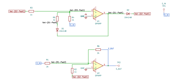
The schematic is drawn by copperhead’s
drafting engine from this circuit’s netlist, with KiCad’s own library symbols,
and it opens in KiCad as figure/full_wave_rectifier.kicad_sch.
The op amp is KiCad’s generic one, since the handbook’s are ideal, and each
terminal is a test point named as the program names it. KiCad reads back from
the sheet exactly the connections the circuit has; draw_figures.py refuses to write
one that does not.
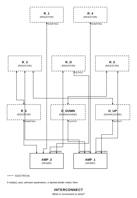
The interconnect view is fang’s own projection. It names the parts as the program does, so it reads against the code below.
What the program says
Section titled “What the program says”The half-wave counts twice as much as E_I at the summer, which is what turns a
half-wave into an absolute value. Its sign depends on the diodes. As drawn
(reading), both point up the page, so a negative E_I gives a half-wave of
+|E_I| and a positive E_I gives zero, and
E_O = -E_I for E_I > 0E_O = -E_I - 2|E_I| = E_I for E_I < 0which is E_O = -|E_I|. Two parameters hold the two slopes to the parts:
a_positive = -R_O/R_1 = -1 and a_negative = -R_O/R_1 + R_O R_3 / (R_2 R_4) = 1.
What the simulation found
Section titled “What the simulation found”| Run | Measured | Claimed |
|---|---|---|
transfer, slope for E_I > 0 | -1 | -1 (a_positive), holds |
transfer, slope for E_I < 0 | 1 | 1 (a_negative), holds |
transfer, E_O at E_I = +10 mV | -9.998 mV | -10 mV ± 0.1 mV, holds |
transfer, E_O at E_I = -10 mV | -9.993 mV | -10 mV ± 0.1 mV, holds |
sine, lowest E_O, 1 V peak in | -1 V | -1 V, holds |
sine, average E_O | -636.6 mV | -2/π V, holds |
Ten millivolts in comes out within 7 µV of ten millivolts: no diode drop shows, which is the point of the circuit against the simple absolute value one.
Where the handbook is off
Section titled “Where the handbook is off”Not off, but not what a reader expects: the drawn diodes give -|E_I|, not +|E_I|. Turned round, both give the positive absolute value. The program keeps the figure and says which sign it gives.
Running it
Section titled “Running it”fang check examples/ti_opamp_handbook/additional/full_wave_rectifier/full_wave_rectifier.pypython examples/regenerate.py ti_opamp_handbook/additional/full_wave_rectifier # needs ngspiceThe whole program
Section titled “The whole program”"""The full wave rectifier, SBOA092B page 89 (top): a precision absolute value.Show 20 more lines
E_O = -(R_O/R_1) E_I - (R_O/R_2) E_H, E_H = half-wave of E_I
The page prints no formula, only "Precision absolute value circuit." The firststage is a precision half-wave rectifier: E_I through R_4 into the summingpoint, R_3 and R_5 back from the output through a diode each, and E_H takenbetween R_3 and its diode. The second stage sums E_I through R_1 (2 kOhm) andE_H through R_2 (1 kOhm) into R_O (2 kOhm), so E_H counts twice as much as E_I.
What the program had to decide is the direction of the diodes, and so the signof the answer. As drawn (`reading`), both diodes point up the page: the upperfrom the first op amp's output to E_H, the lower from R_5 to that output. Anegative E_I then makes E_H = +|E_I|, a positive E_I leaves E_H at zero, and
E_O = -E_I for E_I > 0 E_O = -E_I - 2|E_I| = E_I for E_I < 0
which is E_O = -|E_I|: an absolute value, inverted. Turn both diodes round andit is +|E_I|. The program keeps the drawn diodes and says what they give."""
import sysfrom pathlib import Path
# The handbook's shared parts and bench live in the folder above the sections.sys.path.insert(0, str(Path(__file__).resolve().parents[2]))
from fang.lang import Parameter, System, kOhm, requirefrom fang.parts import Resistorfrom fang.rationale import Chooses, Citesfrom fang.simulation import DCSweep, Transient
from handbook import ( Bench, Claim, Ground, OpAmp, Run, SignalDiode, Terminal, equals, negative, over, product, ratio, total,)
class FullWaveRectifier(System): """A precision half-wave, then a summer that adds it twice to E_I."""
figure = Cites( "Precision absolute value circuit.", document="SBOA092B, Handbook of Operational Amplifier Applications", locator="page 89, Full Wave Rectifier", )
reading = Chooses( "Which way do the two diodes of the first stage point?", selected=( "both up the page, as drawn: the upper from the first op amp's output " "to the R_3/R_2 junction, the lower from R_5 to that output, which " "gives E_O = -|E_I|" ), alternatives=[ { "reading": "both reversed, the textbook circuit", "reason": ( "that gives +|E_I|, but the triangles on the page point up with " "the bar above them; the program does not redraw the figure to " "fit a sign the page never states" ), }, ], rationale=( "the page claims an absolute value and no sign; -|E_I| is one", "the precision, which is the page's point, is the same either way", ), )
a_positive = Parameter( "1", default=-1 * ratio, description="E_O / E_I for E_I > 0: the half-wave is zero, only R_1 counts", ) a_negative = Parameter( "1", default=1 * ratio, description="E_O / E_I for E_I < 0: R_1's -1 plus twice the half-wave's -1", )
e_in = Terminal() e_out = Terminal() r_4 = Resistor(resistance=1 * kOhm) r_3 = Resistor(resistance=1 * kOhm) r_5 = Resistor(resistance=1 * kOhm) d_up = SignalDiode() d_down = SignalDiode() amp_1 = OpAmp() r_1 = Resistor(resistance=2 * kOhm) r_2 = Resistor(resistance=1 * kOhm) r_o = Resistor(resistance=2 * kOhm) amp_2 = OpAmp() ground = Ground()
def architecture(self): # The half-wave stage. self.e_in.probe >> self.r_4.p1 self.r_4.p2 >> self.amp_1.inverting.signal self.amp_1.non_inverting.signal >> self.ground.node self.amp_1.inverting.signal >> self.r_3.p1 self.r_3.p2 >> self.d_up.p2 self.d_up.p1 >> self.amp_1.output.signal self.amp_1.inverting.signal >> self.r_5.p1 self.r_5.p2 >> self.d_down.p1 self.d_down.p2 >> self.amp_1.output.signal
# The summer: E_I through R_1, the half-wave through R_2. self.e_in.probe >> self.r_1.p1 self.r_1.p2 >> self.amp_2.inverting.signal self.r_3.p2 >> self.r_2.p1 self.r_2.p2 >> self.amp_2.inverting.signal self.amp_2.inverting.signal >> self.r_o.p1 self.r_o.p2 >> self.amp_2.output.signal self.amp_2.output.signal >> self.e_out.probe self.amp_2.non_inverting.signal >> self.ground.node
def constraints(self): through_r1 = negative(over(self.r_o.resistance, self.r_1.resistance)) require(equals(self.a_positive, through_r1)) # For E_I < 0 the half-wave is -(R_3/R_4) E_I, and it reaches the output # through R_2 with a gain of -R_O/R_2. require( equals( self.a_negative, total( through_r1, over( product(self.r_o.resistance, self.r_3.resistance), product(self.r_2.resistance, self.r_4.resistance), ), ), ) )
BENCH = Bench( page=89, title="Full Wave Rectifier", runs=[ Run( "transfer", DCSweep(source="VDRIVE_e_in", start="-2", stop="2", step="1m"), drive={"e_in": "DC 0"}, measure={ "e_plus_1": "find v({e_out.1}) at=1", "e_minus_1": "find v({e_out.1}) at=-1", "gain_positive": "e_plus_1 / 1", "gain_negative": "e_minus_1 / -1", "e_plus_10m": "find v({e_out.1}) at=10m", "e_minus_10m": "find v({e_out.1}) at=-10m", }, claims=[ Claim("gain_positive", "a_positive", within=0.001), Claim("gain_negative", "a_negative", within=0.001), Claim("e_plus_10m", -0.01, within=1e-4, absolute=True, unit="V", note="10 mV in, -10 mV out, to 0.1 mV: no diode drop shows"), Claim("e_minus_10m", -0.01, within=1e-4, absolute=True, unit="V"), ], units={"e_plus_1": "V", "e_minus_1": "V"}, ), Run( "sine", Transient(stop="3m", step="1u"), drive={"e_in": "SIN(0 1 1k)"}, measure={ "e_min": "min v({e_out.1}) from=1m to=3m", "e_average": "avg v({e_out.1}) from=1m to=3m", }, claims=[ Claim("e_min", -1, within=0.002, unit="V", note="both peaks of the 1 V sine come out at -1 V"), Claim("e_average", -0.63662, within=0.002, unit="V", note="-2/pi of the peak, the mean of a full-wave rectified sine; " "the 0.2% allows for the few microseconds at each zero " "crossing while the first op amp swings across its diodes"), ], note="E_I is a 1 V peak, 1 kHz sine; the last two cycles are measured.", ), ],)The files it writes
Section titled “The files it writes”The parts, then the nets and the pads on them.
D1 SignalDiode -D2 SignalDiode -GND1 Ground -R1 2 kOhm -R2 1 kOhm -R3 1 kOhm -R4 1 kOhm -R5 1 kOhm -R6 2 kOhm -TP1 Terminal -TP2 Terminal -U1 OpAmp -U2 OpAmp -Net-(D1-PadA) D1.A R5.2Net-(D1-PadK) D1.K D2.A U1.OUTNet-(D2-PadK) D2.K R2.1 R3.2Net-(GND1-Pad1) GND1.1 U1.IN+ U2.IN+Net-(R1-Pad1) R1.1 R4.1 TP1.1Net-(R1-Pad2) R1.2 R2.2 R6.1 U2.IN-Net-(R3-Pad1) R3.1 R4.2 R5.1 U1.IN-Net-(R6-Pad2) R6.2 TP2.1 U2.OUTEvery check that ran, and every one left undecided.
2 checks, 0 failed, 0 undecidedWhat the elaborated graph contains, by entity kind.
1 block 13 component 34 connection 2 constraint 1 decision 1 evidence 3 interface 25 pin 25 port 105 totalsnapshot sha256:ac52e06d6f5c72ac087377e21280cb9cc8ea37ad9b1f26e2756fa15eec1db4f2All of it, including the KiCad netlist, is in
examples/ti_opamp_handbook/additional/full_wave_rectifier/out/. Rebuild it with:
fang build examples/ti_opamp_handbook/additional/full_wave_rectifier/full_wave_rectifier.py