
Examples / TI op amp handbook / Additional circuits
Selective amplifier
SBOA092B page 91, Selective Amplifier: an inverting amplifier with CI (50 nF) and RI (10 kΩ) in series at the input, and RO (330 kΩ) and a twin-T notch (Ra 3.3 kΩ, 2 Ca 100 nF; Ca 50 nF, Ra/2 1.65 kΩ) side by side in the feedback. A notch in the feedback is a peak in the gain.
frequency peak = 1 / (2 π R_a C_a) = 1000 Hzgain at peak = R_O / R_I = 33 = 30 dBZ_in = R_I = 10 kΩ, Z_out < 200 ΩThe circuit
Section titled “The circuit”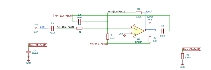
The schematic is drawn by copperhead’s
drafting engine from this circuit’s netlist, with KiCad’s own library symbols,
and it opens in KiCad as figure/selective_amplifier.kicad_sch.
The op amp is KiCad’s generic one, since the handbook’s are ideal, and each
terminal is a test point named as the program names it. KiCad reads back from
the sheet exactly the connections the circuit has; draw_figures.py refuses to write
one that does not.
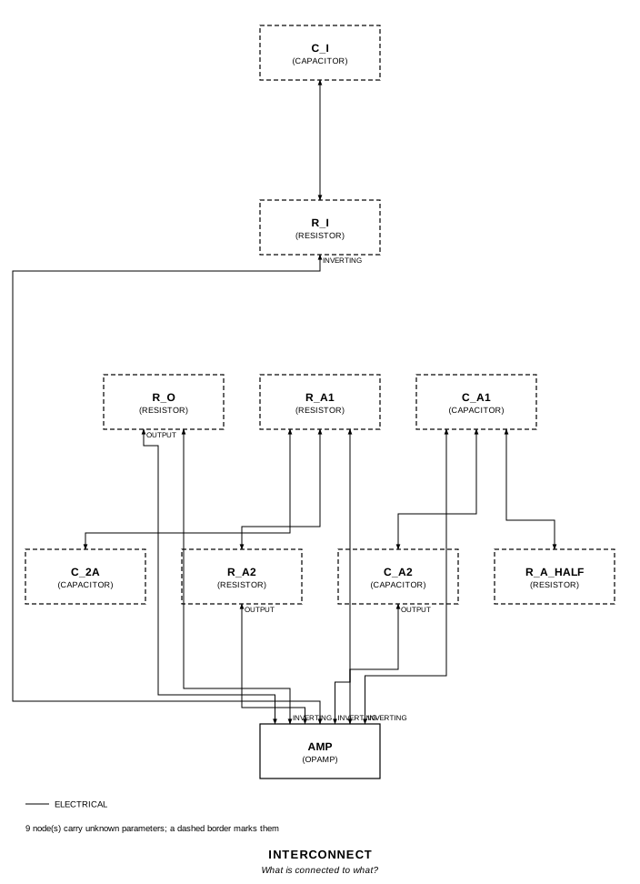
The interconnect view is fang’s own projection. It names the parts as the program does, so it reads against the code below.
What the program says
Section titled “What the program says”It keeps the drawn values and holds four numbers to them: f_notch
(1/(2π R_a C_a) = 964.6 Hz), a_ideal (R_O / R_I = 33, the page’s), z_in
(|R_I + 1/(j 2π f C_I)| at the notch, 10.53 kΩ) and a_notch (R_O / |Z_in|
there, 31.34). The twin-T’s balance (2 C_a, R_a/2) and the page’s rule
C_I R_I > 2 C_a R_a (500 µs against 330 µs) are constraints too.
What the simulation found
Section titled “What the simulation found”out/simulation.txt, a linear sweep 900 Hz to 1050 Hz in
0.05 Hz steps:
| Measured | Value | Claimed |
|---|---|---|
| gain at the notch, 964.6 Hz | 31.66 | 31.34 (a_notch) ± 2%, holds |
| input impedance at the notch | 10.52 kΩ | 10.53 kΩ (z_in) ± 0.5%, holds |
| centre of the -3 dB band | 973.9 Hz | 964.6 Hz (f_notch) ± 2%, holds |
| gain at the top of the peak | 44.05 (32.9 dB) | not a claim |
| -3 dB band | 964.3 to 983.6 Hz | not a claim |
The gain climbs 1.6 per hertz at the notch, so 2% there is about 0.2 Hz of where the simulated notch falls.
Where the handbook is off
Section titled “Where the handbook is off”- 1/(2π 3.3 kΩ 50 nF) is 964.6 Hz, not 1000 Hz; the peak itself sits 1% above that, at 974 Hz.
- C_I’s reactance at the notch is exactly R_a, 3.3 kΩ (C_I equals C_a), so the input impedance is 10.53 kΩ, not R_I, and the gain at the notch is 31.3 (29.9 dB), not 33.
- The top of the peak is higher still, 44 (32.9 dB): a few hertz above the notch the twin-T’s transfer admittance has a negative real part, which cancels part of R_O’s conductance. The page’s 30 dB is closer to the gain at the notch than at the peak.
- Z_out < 200 Ω is not checked: the bench’s op amp has an ideal output.
Running it
Section titled “Running it”fang check examples/ti_opamp_handbook/additional/selective_amplifier/selective_amplifier.pypython examples/regenerate.py ti_opamp_handbook/additional/selective_amplifier # needs ngspiceThe whole program
Section titled “The whole program”"""The selective amplifier, SBOA092B page 91.Show 23 more lines
frequency peak = 1 / (2 pi R_a C_a) = 1000 Hz gain at peak = R_O / R_I = 33 = 30 dB
An inverting amplifier with a twin-T notch in its feedback. E_I arrives throughC_I (50 nF) and R_I (10 kOhm) in series; R_O (330 kOhm) and the twin-T sitside by side from the summing point to the output. At the notch frequency thetwin-T passes nothing, the feedback is R_O alone, and the gain peaks; eitherside of it the twin-T shorts the output back to the summing point and the gainfalls away.
Two things the page rounds, and the program keeps the drawn values:
- 1 / (2 pi 3.3 kOhm 50 nF) is 964.6 Hz, which the page prints as 1000 Hz.- R_O / R_I is 33, but E_I reaches the summing point through C_I as well, and at the notch C_I's reactance is 1 / (2 pi f C_I) = R_a = 3.3 kOhm (C_I is the same 50 nF as C_a). The input impedance there is |10k - j 3.3k| = 10.53 kOhm, not R_I, and the gain is 330k / 10.53k = 31.3, which is 29.9 dB: the page's 30 dB holds, its 33 does not.
The page's rule for C_I, C_I R_I > 2 C_a R_a, is met (500 us against 330 us),and is a constraint below."""
import sysfrom pathlib import Path
# The handbook's shared parts and bench live in the folder above the sections.sys.path.insert(0, str(Path(__file__).resolve().parents[2]))
from fang.lang import Hz, Ohm, Parameter, System, kOhm, nF, requirefrom fang.parts import Capacitor, Resistorfrom fang.rationale import Calculates, Chooses, Citesfrom fang.simulation import ACSweep
from handbook import ( TWO_PI, Bench, Claim, Ground, OpAmp, Run, Terminal, at_least, at_most, corner, equals, over, product, ratio, total, within,)
class SelectiveAmplifier(System): """C_I and R_I in, R_O and a twin-T notch across."""
figure = Cites( "Frequency peak = 1/(2 pi R_a C_a) = 1000 Hz. Gain at peak = R_O/R_I = 33 " "= 30 dB. Set C_I so that C_I R_I > 2 C_a R_a and R_I < 100 kOhm. " "Z_in = R_I = 10 kOhm. Z_out < 200 Ohm.", document="SBOA092B, Handbook of Operational Amplifier Applications", locator="page 91, Selective Amplifier", )
reading = Chooses( "How is the twin-T wired?", selected=( "from the summing point to the output: R_a, R_a in series with 2 C_a " "from their junction to ground, beside C_a, C_a in series with R_a/2 " "from their junction to ground" ), alternatives=[ { "reading": "the twin-T in the input path", "reason": ( "its two outer nodes are on the summing point and on E_O, beside " "R_O; in the input it would notch, not peak" ), }, ], rationale=( "the page calls it twin T feedback, and a notch in the feedback is a " "peak in the gain", ), )
notch = Calculates( "f = 1 / (2 pi R_a C_a)", inputs=("r_a1", "c_a1"), result="964.6 Hz; the page prints 1000 Hz", )
at_peak = Calculates( "|A| = R_O / |R_I + 1 / (j 2 pi f C_I)| at the notch", inputs=("r_o", "r_i", "c_i"), result=( "C_I's reactance at 964.6 Hz is 3.3 kOhm, so |Z_in| = 10.53 kOhm and " "|A| = 31.34 (29.9 dB); the page's R_O / R_I = 33 leaves C_I out" ), )
f_notch = Parameter("Hz", default=964.6 * Hz, description="1/(2 pi R_a C_a)") a_ideal = Parameter("1", default=33 * ratio, description="R_O / R_I, as the page has it") z_in = Parameter( "Ohm", default=10530 * Ohm, description="|R_I + 1/(j 2 pi f C_I)| at the notch", ) a_notch = Parameter( "1", default=31.34 * ratio, description="R_O / |Z_in| at the notch: the gain the circuit has there", )
e_in = Terminal() e_out = Terminal() c_i = Capacitor(capacitance=50 * nF) r_i = Resistor(resistance=10 * kOhm) r_o = Resistor(resistance=330 * kOhm) r_a1 = Resistor(resistance=3.3 * kOhm) r_a2 = Resistor(resistance=3.3 * kOhm) c_2a = Capacitor(capacitance=100 * nF) c_a1 = Capacitor(capacitance=50 * nF) c_a2 = Capacitor(capacitance=50 * nF) r_a_half = Resistor(resistance=1.65 * kOhm) amp = OpAmp() ground = Ground()
def architecture(self): self.e_in.probe >> self.c_i.p1 self.c_i.p2 >> self.r_i.p1 self.r_i.p2 >> self.amp.inverting.signal self.amp.non_inverting.signal >> self.ground.node self.amp.inverting.signal >> self.r_o.p1 self.r_o.p2 >> self.amp.output.signal self.amp.output.signal >> self.e_out.probe
# The resistive T: R_a, R_a, and 2 C_a to ground from the middle. self.amp.inverting.signal >> self.r_a1.p1 self.r_a1.p2 >> self.r_a2.p1 self.r_a2.p2 >> self.amp.output.signal self.r_a1.p2 >> self.c_2a.p1 self.c_2a.p2 >> self.ground.node
# The capacitive T: C_a, C_a, and R_a/2 to ground from the middle. self.amp.inverting.signal >> self.c_a1.p1 self.c_a1.p2 >> self.c_a2.p1 self.c_a2.p2 >> self.amp.output.signal self.c_a1.p2 >> self.r_a_half.p1 self.r_a_half.p2 >> self.ground.node
def constraints(self): # A balanced twin-T, which is what makes the notch deep. require(equals(self.r_a2.resistance, self.r_a1.resistance)) require(equals(self.c_a2.capacitance, self.c_a1.capacitance)) require(equals(self.c_2a.capacitance, product(2 * ratio, self.c_a1.capacitance))) require(equals(self.r_a_half.resistance, over(self.r_a1.resistance, 2 * ratio)))
# The page's rule for C_I, and its ceiling on R_I. require( at_least( product(self.c_i.capacitance, self.r_i.resistance), product(2 * ratio, self.c_a1.capacitance, self.r_a1.resistance), ) ) require(at_most(self.r_i.resistance, 100 * kOhm))
require(within(self.f_notch, corner(self.r_a1.resistance, self.c_a1.capacitance), 0.001)) require(equals(self.a_ideal, over(self.r_o.resistance, self.r_i.resistance)))
# |Z_in|^2 = R_I^2 + X^2, with X = 1/(2 pi f C_I) at the notch. reactance = over(1 * ratio, product(TWO_PI, self.f_notch, self.c_i.capacitance)) z_squared = total( product(self.r_i.resistance, self.r_i.resistance), product(reactance, reactance), ) require(within(product(self.z_in, self.z_in), z_squared, 0.001)) require( within( product(self.a_notch, self.a_notch, z_squared), product(self.r_o.resistance, self.r_o.resistance), 0.001, ) )
BENCH = Bench( page=91, title="Selective Amplifier", runs=[ Run( "around_the_peak", ACSweep(variation="lin", points=3001, start="900", stop="1050"), drive={"e_in": "DC 0 AC 1"}, measure={ "gain_notch": "find vm({e_out.1}) at=964.57", "v_r_i": "find vm({r_i.1}) at=964.57", "z_in_notch": "10000 / v_r_i", "gain_peak": "max vm({e_out.1})", "gain_peak_db": "max vdb({e_out.1})", "half_power": "gain_peak * 0.70711", "f_low": "when vm({e_out.1})=half_power rise=1", "f_high": "when vm({e_out.1})=half_power fall=1", "f_centre": "sqrt(f_low * f_high)", }, claims=[ Claim("gain_notch", "a_notch", within=0.02, note="at the notch, 964.6 Hz: R_O over |Z_in|. The page's " "R_O / R_I = 33 leaves out C_I's 3.3 kOhm of reactance. 2%, " "because the gain climbs 1.6 per hertz here and the simulated " "notch sits about 0.2 Hz below 1/(2 pi R_a C_a)"), Claim("z_in_notch", "z_in", within=0.005, unit="Ohm", note="1 V over the current through R_I, at the notch. The page " "says Z_in = R_I = 10 kOhm, which leaves out C_I. 0.5%, because " "the current is read as the voltage at R_I's input end over " "10 kOhm, and the summing point is a few millivolts off ground " "with 80 dB of open-loop gain at 1 kHz"), Claim("f_centre", "f_notch", within=0.02, unit="Hz", note="the middle of the -3 dB band, 1% above the notch. The page " "prints 1000 Hz; 1/(2 pi R_a C_a) is 964.6 Hz"), ], units={"v_r_i": "V", "f_low": "Hz", "f_high": "Hz", "gain_peak_db": "dB"}, note=( "A linear sweep, 0.05 Hz a step, from 900 Hz to 1050 Hz. The peak is " "sharp, about 20 Hz wide, and sits a few hertz above the notch: there " "the twin-T's transfer admittance has a negative real part that " "cancels part of R_O's conductance, so the gain at the top is higher " "than R_O / |Z_in|: 44, where the page says 33." ), ), ],)The files it writes
Section titled “The files it writes”The parts, then the nets and the pads on them.
C1 100 nF -C2 50 nF -C3 50 nF -C4 50 nF -GND1 Ground -R1 3.3 kOhm -R2 3.3 kOhm -R3 1.65 kOhm -R4 10 kOhm -R5 330 kOhm -TP1 Terminal -TP2 Terminal -U1 OpAmp -Net-(C1-Pad1) C1.1 R1.2 R2.1Net-(C1-Pad2) C1.2 GND1.1 R3.2 U1.IN+Net-(C2-Pad1) C2.1 R1.1 R4.2 R5.1 U1.IN-Net-(C2-Pad2) C2.2 C3.1 R3.1Net-(C3-Pad2) C3.2 R2.2 R5.2 TP2.1 U1.OUTNet-(C4-Pad1) C4.1 TP1.1Net-(C4-Pad2) C4.2 R4.1Every check that ran, and every one left undecided.
10 checks, 0 failed, 0 undecidedWhat the elaborated graph contains, by entity kind.
1 block 2 calculation 13 component 34 connection 10 constraint 1 decision 1 evidence 3 interface 24 pin 24 port 113 totalsnapshot sha256:952ae00aad3d72b16242705e555640f1d9d22c0170c85d8d94cd74928975bd22All of it, including the KiCad netlist, is in
examples/ti_opamp_handbook/additional/selective_amplifier/out/. Rebuild it with:
fang build examples/ti_opamp_handbook/additional/selective_amplifier/selective_amplifier.py