
Examples / TI op amp handbook / DC amplifiers
Power booster
SBOA092B pages 71 and 72, Power Booster: a compound amplifier. A precision OPA277 runs the outer loop at G = 1 + 20k/1k = +21; a power OPA512 inside it runs a local loop at 1 + 10k/4.7k = 3.13 (10 pF across its 10 kΩ); two 0.1 Ω in parallel sit between the OPA512 and EO, inside both loops; 47 pF from the OPA277's output to its - input adds phase lead for stability. EI is on the OPA277's + input with 100 kΩ to ground.
G = +21Table 1, compound: V_OS 20 µV, V_OUT ±35 V, I_OUT 10 A, SR 2.4 V/µsThe circuit
Section titled “The circuit”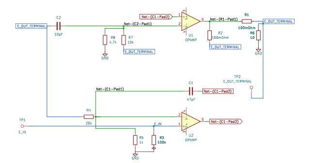
The schematic is drawn by copperhead’s
drafting engine from this circuit’s netlist, with KiCad’s own library symbols,
and it opens in KiCad as figure/power_booster.kicad_sch.
The op amp is KiCad’s generic one, since the handbook’s are ideal, and each
terminal is a test point named as the program names it. KiCad reads back from
the sheet exactly the connections the circuit has; draw_figures.py refuses to write
one that does not.

The interconnect view is fang’s own projection. It names the parts as the program does, so it reads against the code below.
What the program says
Section titled “What the program says”models gives each op amp its column of Table 1: the OPA277 swings ±13 V
with 20 µV of offset, the OPA512 ±35 V with 6 mV. The table gives no
bandwidth, so the gain-bandwidths are the parts’ data-sheet figures, 1 MHz
and 4 MHz. The macro-model has no slew rate or current limit, so those rows
are recorded and not simulated. load adds the 10 Ω the figure does not
draw. The constraints hold G = 21 and the local 3.13 to the resistors; say
that 30 V out needs 1.4286 V in, is beyond the OPA277’s own +13 V and inside
the OPA512’s +35 V, while the OPA277 itself supplies only E_O / 3.13 = 9.6 V;
and put the compound’s output offset at 21 times the OPA277’s.
What the simulation found
Section titled “What the simulation found”out/simulation.txt, from the decks under
out/spice/:
| Run | Measured | Claimed |
|---|---|---|
thirty_volts, gain, E_I = 1.4286 V into 10 Ω | 21 | 21 (g), holds |
thirty_volts, E_O | 30 V (3 A) | 30 V (e_out), holds |
thirty_volts, OPA277 output | 9.598 V | 9.6 V (e_front), holds |
thirty_volts, OPA512 output | 30.15 V | not a claim |
offset, E_O with E_I = 0 | -420.1 µV | -420 µV (v_os_out), holds |
stability, gain at 100 Hz | 26.44 dB | 20 log 21, holds |
stability, peak above the DC gain | 0 dB | at most 1 dB, holds |
stability, -3 dB point | 139 kHz | not a claim |
step, 0.1 V step, final value | 2.1 V | 2.1 V, holds |
step, overshoot | 0 | under 5%, holds |
The OPA277 swings 9.6 V while the load gets 30 V and 3 A, and the output offset is the OPA277’s 20 µV times 21 (negative here only because the model subtracts its offset from the + input); the OPA512’s 6 mV shows up at the OPA277’s output, not at E_O. With single-pole models at 1 MHz and 4 MHz the two loops do not peak and the step does not overshoot: the response is monotonic, rolling off at 139 kHz. That is a statement about these models; a real OPA512’s extra poles and its slew rate are not in them.
Running it
Section titled “Running it”fang check examples/ti_opamp_handbook/dc_amplifiers/power_booster/power_booster.pypython examples/regenerate.py ti_opamp_handbook/dc_amplifiers/power_booster # needs ngspiceThe whole program
Section titled “The whole program”"""The power booster, a compound amplifier, SBOA092B pages 71 and 72.Show 21 more lines
G = 1 + 20k / 1k = +21
Page 71 says any of the circuits before it can drive more current if a powerbooster is put inside its loop; page 72 draws one. A precision OPA277 runsthe outer loop: E_I reaches its + input across 100 kOhm to ground, and 20 kOhmfrom the final output over 1 kOhm to ground sets the gain at 21. A powerOPA512 inside that loop runs a local one: its + input is the OPA277's output,and 10 kOhm with 10 pF across it, over 4.7 kOhm to ground, make it a gain of1 + 10k/4.7k = 3.13. Two 0.1 Ohm in parallel sit between the OPA512 and E_O,inside both loops, and 47 pF from the OPA277's output to its - input adds the"small amount of phase shift to help stabilize the system".
The point of the figure is Table 1: the compound keeps the OPA277's 20 uV ofoffset and reaches the OPA512's +/-35 V. The program models each op amp withits column of the table (`models`), and the claims are that the gain is 21,that 30 V reaches the load while the OPA277 swings only 9.6 V, which isinside its own +/-13 V, that the output offset is the OPA277's times 21, andthat the two loops together are stable. The load is not drawn; `load` is theprogram's."""
import sysfrom decimal import Decimalfrom pathlib import Path
# The handbook's shared parts and bench live in the folder above the sections.sys.path.insert(0, str(Path(__file__).resolve().parents[2]))
from fang.lang import MHz, Ohm, Parameter, System, V, kOhm, mOhm, mV, pF, require, uVfrom fang.parts import Capacitor, Resistorfrom fang.rationale import Chooses, Citesfrom fang.simulation import ACSweep, OperatingPoint, Transient
from handbook import ( Bench, Claim, Ground, OpAmp, Run, Terminal, at_least, at_most, equals, negative, over, product, ratio, total, within,)
class PowerBooster(System): """OPA277 in the outer loop at a gain of 21, OPA512 in a local loop inside it."""
figure = Cites( "G = +21. The compound amplifier: V_OS 20 uV, V_OUT +/-35 V, I_OUT 10 A " "(Table 1). The 47pF capacitor provides a small amount of phase shift " "to help stabilize the system.", document="SBOA092B, Handbook of Operational Amplifier Applications", locator="page 72, Power Booster (Table 1, Compound Amplifier, Resulting Performance)", )
models = Chooses( "What does each op amp's model hold?", selected=( "Table 1's columns: OPA277 +/-13 V swing and 20 uV offset, OPA512 " "+/-35 V swing and 6 mV offset; gain-bandwidth 1 MHz for the " "OPA277 and 4 MHz for the OPA512, from their data sheets; open-loop " "gain left at the bench's 120 dB" ), alternatives=[ { "option": "the bench's default op amp for both", "reason": ( "its +/-13.5 V swing is the very limit the booster exists " "to pass, and its 10 MHz would hide whether the two loops " "are stable at the parts' real speeds" ), }, { "option": "model slew rate and output current limit too", "reason": ( "the bench's macro-model has neither; the table's 2.4 V/us " "and 10 A are recorded here and not simulated" ), }, ], rationale=( "the table gives swing and offset for each part", "the table gives no bandwidth; 1 MHz and 4 MHz are the OPA277's and OPA512's data-sheet figures", ), )
load = Chooses( "What does E_O drive?", selected="10 Ohm to ground, so 30 V out is 3 A, well past the OPA277's 5 mA", alternatives=[ { "option": "no load", "reason": "a power stage with nothing to drive shows nothing a single OPA277 could not do, except swing", }, { "option": "a lower resistance, near the 10 A the table allows", "reason": "the macro-model has no current limit, so a heavier load would prove nothing more", }, ], rationale=("the figure draws no load",), )
g = Parameter("1", default=21 * ratio, description="E_O / E_I, the outer loop") g_local = Parameter("1", default=Decimal("3.13") * ratio, description="the OPA512's own gain, rounded") e_drive = Parameter("V", default=Decimal("1.4286") * V, description="the bench's E_I") e_out = Parameter("V", default=30 * V, description="what that E_I puts across the load") e_front = Parameter("V", default=Decimal("9.6") * V, description="the OPA277's output meanwhile") v_os_out = Parameter("V", default=-420 * uV, description="E_O with E_I at zero")
e_in = Terminal() e_out_terminal = Terminal() r_bias = Resistor(resistance=100 * kOhm) r_ground = Resistor(resistance=1 * kOhm) r_feedback = Resistor(resistance=20 * kOhm) c_front = Capacitor(capacitance=47 * pF) r_local_ground = Resistor(resistance=Decimal("4.7") * kOhm) r_local = Resistor(resistance=10 * kOhm) c_local = Capacitor(capacitance=10 * pF) r_ballast_a = Resistor(resistance=100 * mOhm) r_ballast_b = Resistor(resistance=100 * mOhm) r_load = Resistor(resistance=10 * Ohm) front = OpAmp( gain_bandwidth=1 * MHz, output_high=13 * V, output_low=-13 * V, input_offset=20 * uV, ) booster = OpAmp( gain_bandwidth=4 * MHz, output_high=35 * V, output_low=-35 * V, input_offset=6 * mV, ) ground = Ground()
def architecture(self): # The OPA277: E_I on its + input, the outer loop on its - input. self.e_in.probe >> self.front.non_inverting.signal self.front.non_inverting.signal >> self.r_bias.p1 self.front.inverting.signal >> self.r_ground.p1 self.front.inverting.signal >> self.r_feedback.p1 self.front.inverting.signal >> self.c_front.p1 self.c_front.p2 >> self.front.output.signal
# The OPA512, driven by the OPA277, with its own loop from E_O. self.front.output.signal >> self.booster.non_inverting.signal self.booster.inverting.signal >> self.r_local_ground.p1 self.booster.inverting.signal >> self.r_local.p1 self.booster.inverting.signal >> self.c_local.p1
# The two 0.1 Ohm from the OPA512 to E_O, and everything E_O feeds. self.booster.output.signal >> self.r_ballast_a.p1 self.booster.output.signal >> self.r_ballast_b.p1 self.r_ballast_a.p2 >> self.e_out_terminal.probe self.r_ballast_b.p2 >> self.e_out_terminal.probe self.e_out_terminal.probe >> self.r_local.p2 self.e_out_terminal.probe >> self.c_local.p2 self.e_out_terminal.probe >> self.r_feedback.p2 self.e_out_terminal.probe >> self.r_load.p1
self.r_bias.p2 >> self.ground.node self.r_ground.p2 >> self.ground.node self.r_local_ground.p2 >> self.ground.node self.r_load.p2 >> self.ground.node
def constraints(self): require( equals( self.g, total(1 * ratio, over(self.r_feedback.resistance, self.r_ground.resistance)), ) ) require( within( self.g_local, total(1 * ratio, over(self.r_local.resistance, self.r_local_ground.resistance)), 0.001, ) ) # 30 V out for the bench's drive, past the OPA277's own swing and # inside the OPA512's, while the OPA277 supplies only E_O / 3.13. require(within(self.e_out, product(self.g, self.e_drive), 0.001)) require(at_least(self.e_out, self.front.output_high)) require(at_most(self.e_out, self.booster.output_high)) require(within(self.e_front, over(self.e_out, self.g_local), 0.005)) require(at_most(self.e_front, self.front.output_high)) # The compound's offset is the OPA277's, times the outer gain. The # macro-model subtracts its offset from the + input, so a positive # offset shows as a negative output. require(equals(self.v_os_out, negative(product(self.g, self.front.input_offset))))
BENCH = Bench( page=72, title="Power Booster", runs=[ Run( "thirty_volts", OperatingPoint(), drive={"e_in": "DC 1.4286"}, measure={ "gain": "v({e_out_terminal.1}) / v({e_in.1})", "e_out": "v({e_out_terminal.1})", "e_front": "v({front.OUT})", "i_load": "v({e_out_terminal.1}) / 10", "e_booster": "v({booster.OUT})", }, claims=[ Claim( "gain", "g", within=0.001, note="the OPA277's 20 uV offset, times 21, moves this by 0.001%", ), Claim("e_out", "e_out", within=0.001, unit="V"), Claim( "e_front", "e_front", within=0.005, unit="V", note=( "30 V x 4.7k / 14.7k is 9.592 V, plus the OPA512's 6 mV " "of offset, which its own input carries; the claim " "rounds to 9.6 V, hence 0.5%" ), ), ], units={"e_booster": "V", "i_load": "A"}, note=( "E_I = 1.4286 V into a 10 Ohm load. The OPA277 alone would stop " "at 13 V; here it swings 9.6 V while E_O reaches 30 V and 3 A." ), ), Run( "offset", OperatingPoint(), drive={"e_in": "DC 0"}, measure={"v_os_out": "v({e_out_terminal.1})"}, claims=[ Claim( "v_os_out", "v_os_out", within=0.01, unit="V", note=( "21 x the OPA277's 20 uV, negative because the model " "subtracts its offset from the + input. The OPA512's " "6 mV is inside the outer loop and divided by the " "OPA277's gain" ), ) ], ), Run( "stability", ACSweep(points=40, start="10", stop="100meg"), drive={"e_in": "DC 0 AC 1"}, measure={ "gain_db": "find vdb({e_out_terminal.1}) at=100", "peak_db": "max vdb({e_out_terminal.1}) from=10 to=100meg", "f_3db": "when vdb({e_out_terminal.1})=23.44 fall=1", "peaking": "peak_db - gain_db", }, claims=[ Claim("gain_db", 26.444, within=0.01, absolute=True, note="20 log 21"), Claim( "peaking", 0, within=1, absolute=True,
note="no more than 1 dB of peak above the DC gain: the two loops together do not ring", ), ], units={"f_3db": "Hz"}, note=( "The -3 dB point is not a handbook claim; it is where the " "OPA277's 1 MHz, over a noise gain of 21 and helped by the " "OPA512's 3.13, runs out." ), ), Run( "step", Transient(stop="40u", step="10n"), drive={"e_in": "PULSE(0 0.1 1u 10n 10n 100u 200u)"}, measure={ "final": "find v({e_out_terminal.1}) at=39u", "peak": "max v({e_out_terminal.1}) from=1u to=39u", "overshoot": "(peak - final) / final", }, claims=[ Claim("final", 2.1, within=0.001, unit="V", note="21 x 0.1 V"), Claim( "overshoot", 0, within=0.05, absolute=True, note="a 0.1 V step settles with under 5% overshoot", ), ], units={"peak": "V"}, note="A small step, so the missing slew limit does not matter.", ), ],)The files it writes
Section titled “The files it writes”The parts, then the nets and the pads on them.
C1 47 pF -C2 10 pF -GND1 Ground -R1 100 mOhm -R2 100 mOhm -R3 100 kOhm -R4 20 kOhm -R5 1 kOhm -R6 10 Ohm -R7 10 kOhm -R8 4.7 kOhm -TP1 Terminal -TP2 Terminal -U1 OpAmp -U2 OpAmp -Net-(C1-Pad1) C1.1 R4.1 R5.1 U2.IN-Net-(C1-Pad2) C1.2 U1.IN+ U2.OUTNet-(C2-Pad1) C2.1 R7.1 R8.1 U1.IN-Net-(C2-Pad2) C2.2 R1.2 R2.2 R4.2 R6.1 R7.2 TP2.1Net-(GND1-Pad1) GND1.1 R3.2 R5.2 R6.2 R8.2Net-(R1-Pad1) R1.1 R2.1 U1.OUTNet-(R3-Pad1) R3.1 TP1.1 U2.IN+Every check that ran, and every one left undecided.
8 checks, 0 failed, 0 undecidedWhat the elaborated graph contains, by entity kind.
1 block 15 component 44 connection 8 constraint 2 decision 1 evidence 3 interface 29 pin 29 port 132 totalsnapshot sha256:c4f10de51d0312fc6bc5a515313acebfb468d993eabbbf2f96461292d6a366bdAll of it, including the KiCad netlist, is in
examples/ti_opamp_handbook/dc_amplifiers/power_booster/out/. Rebuild it with:
fang build examples/ti_opamp_handbook/dc_amplifiers/power_booster/power_booster.py