
Examples / TI op amp handbook / Integrators
Zeroed integrator
SBOA092B page 56, Simple Integrators (the second figure). This is the integrator above it, R1 100 kΩ into the summing point with CO and a reset switch, plus a trimmed current into the summing point. The + and - terminals feed the ends of the pot R3 through R2 and R4 (10 kΩ each), and the wiper reaches the summing point through R5 (10 MΩ). "With zero input and switch open, set R3 for zero output drift."
The circuit
Section titled “The circuit”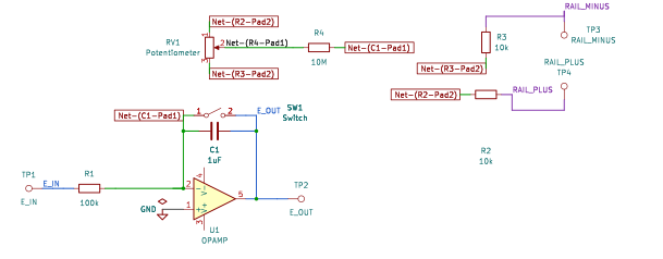
The schematic is drawn by copperhead’s
drafting engine from this circuit’s netlist, with KiCad’s own library symbols,
and it opens in KiCad as figure/zeroed_integrator.kicad_sch.
The op amp is KiCad’s generic one, since the handbook’s are ideal, and each
terminal is a test point named as the program names it. KiCad reads back from
the sheet exactly the connections the circuit has; draw_figures.py refuses to write
one that does not.
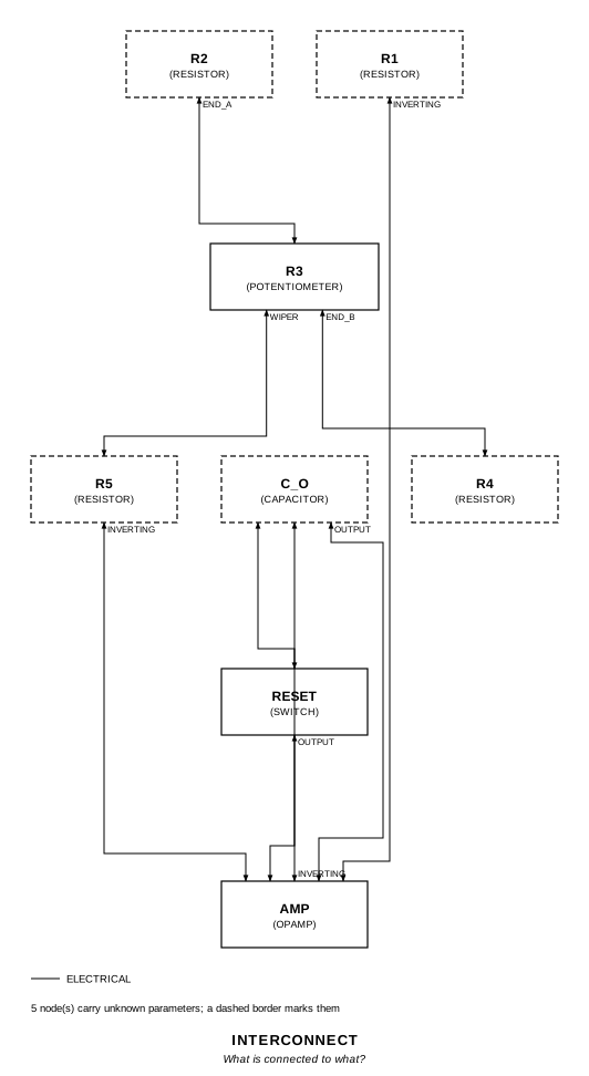
The interconnect view is fang’s own projection. It names the parts as the program does, so it reads against the code below.
What the program says
Section titled “What the program says”The figure leaves four things open, and the program records each one as a decision:
c_o_reading: C_O is printed “1 mF” and is read as 1 µF. Every other integrator on these pages pairs 100 kΩ with 1 µF. -1/(R1 C_O) is -10 /s with 1 µF and -0.01 /s with 1 mF (either_reading).network: R3 is 10 kΩ, and + and - are the ±15 V rails, so the wiper spans -5 V to +5 V.error: the op amp model has no bias-current term, so it is given a 1 mV input offset instead. Across R1 that is 10 nA into C_O, the same current offset the handbook describes.
The constraints solve for the null. The wiper has to sit at
-Vos (1 + R5/R1) = -101 mV (v_wiper_null), and on the R2-R3-R4 chain that
is a setting of 0.5101. The program sets R3 there, and drift_centred
(-10.1 mV/s) is the drift with the wiper at its centre.
What the simulation found
Section titled “What the simulation found”out/simulation.txt, from the decks under out/spice/.
Zero input, reset switch open from 10 ms:
| Run | R3 setting | Wiper | Drift | Claimed |
|---|---|---|---|---|
centred | 0.5 | 0 V | -10.1 mV/s | -10.1 mV/s (drift_centred), holds |
nulled | 0.5101 | -100.9 mV | -7.5 µV/s | 0 ± 0.1 mV/s, holds |
past_null | 0.55 | -0.5 V | +39.9 mV/s | +39.9 mV/s, holds |
short_of_null | 0.45 | +0.5 V | -60.1 mV/s | -60.1 mV/s, holds |
rate (E_I = 0.1 V, nulled) | 0.5101 | -10 /s per volt | -10 /s (rate), holds |
The pot can send current of either sign into the summing point, and at the solved setting the drift is 0.07% of what it is with the wiper centred.
Where the handbook is off
Section titled “Where the handbook is off”The figure prints C_O as “1 mF”. Taken literally, the integrator would run at -0.01 V/s per volt rather than the -10 of the figure above it. The program simulates 1 µF and says so.
Running it
Section titled “Running it”fang check examples/ti_opamp_handbook/integrators/zeroed_integrator/zeroed_integrator.pypython examples/regenerate.py ti_opamp_handbook/integrators/zeroed_integrator # needs ngspiceThe whole program
Section titled “The whole program”"""The integrator with an offset-current null, SBOA092B page 56 (bottom).Show 20 more lines
E_O = -1/(R1 C_O) integral E_I dt, with R3 set for zero output drift
R1 (100 kOhm) and C_O make the integrator of the figure above it, with the samereset switch. The addition is a current source for the summing point: the +and - terminals feed the two ends of the pot R3 through R2 and R4 (10 kOhmeach), and the wiper reaches the summing point through R5 (10 MOhm). Thehandbook: "With zero input and switch open, set R3 for zero output drift."
The program had to decide four things the figure leaves open, each recorded asa decision. C_O is printed "1 mF", read as 1 uF (`c_o_reading`). R3 has novalue; it is 10 kOhm, and the + and - terminals are the +/-15 V rails(`network`). And the op amp needs an error for the pot to cancel: the modelhas no bias-current term, so it is given a 1 mV input offset (`error`), whichacross R1 is the 10 nA a bias current would be, stored in C_O the same way.
The runs show the drift with the wiper centred (-10.1 mV/s), the pot at thesetting the constraints solve for (no drift), the pot either side of it(drift of either sign), and the integration rate with the drift nulled."""
import sysfrom decimal import Decimalfrom pathlib import Path
# The handbook's shared parts and bench live in the folder above the sections.sys.path.insert(0, str(Path(__file__).resolve().parents[2]))
from fang.lang import MOhm, Parameter, System, UnitLiteral, V, kOhm, mV, require, uFfrom fang.parts import Capacitor, Resistorfrom fang.rationale import Calculates, Chooses, Citesfrom fang.simulation import Transient
from handbook import ( Bench, Claim, Ground, OpAmp, Potentiometer, Run, Switch, Terminal, equals, minus, negative, over, product, ratio, total, within,)
#: A rate: volts of output per second, for each volt of input.per_second = UnitLiteral("1/s")#: A drift: volts of output per second.volts_per_second = UnitLiteral("V/s")
#: The reset: closed at t = 0, open from 10 ms.RESET = "PWL(0 1 10m 1 10.001m 0)"#: The + and - terminals, which the program reads as the +/-15 V rails.RAILS = {"rail_plus": "DC 15", "rail_minus": "DC -15"}
class ZeroedIntegrator(System): """An integrator whose summing point also takes a trimmed current from the rails."""
figure = Cites( "This circuit reduces current offset in operational amplifiers without " "\"Balance\" controls. With zero input and switch open, set R3 for zero " "output drift. (R1 100 kOhm, C_O 1 mF, R2 and R4 10 kOhm, R3 POT, R5 10 MOhm)", document="SBOA092B, Handbook of Operational Amplifier Applications", locator="page 56, Simple Integrators (second figure)", )
c_o_reading = Chooses( "C_O is printed \"1 mF\". Is that 1 millifarad?", selected="1 uF, a misprint: the simulation uses 1 uF", alternatives=[ { "option": "1 mF as printed", "reason": ( "every other integrator on pages 56 to 59 pairs 100 kOhm with " "1 uF, and a 1 mF film or polystyrene integrating capacitor is " "not a part anyone would reset through a switch" ), }, ], rationale=( "the same page's first figure is R_I 100 kOhm and C_O 1 uF for -10 integral E_I dt", "older schematics wrote mF and mfd for microfarads, and the label reads like one of those", ), )
either_reading = Calculates( "-1/(R1 C_O)", inputs=("r1", "c_o"), result=( "-10 per second with 1 uF, as simulated; -0.01 per second with 1 mF " "as printed" ), )
network = Chooses( "What are R3, and the + and - terminals?", selected="R3 is 10 kOhm; + and - are the +/-15 V supply rails", alternatives=[ { "option": "a separate reference pair", "reason": "the figure draws only terminals, and a zero control is fed from the rails", }, ], rationale=( "with 10 kOhm the chain R2, R3, R4 is 30 kOhm across 30 V, and the " "wiper spans -5 V to +5 V: up to 0.5 uA either way through R5, fifty " "times the error it has to cancel", "the page 57 zero control uses a 10 kOhm pot between 10 kOhm resistors, the same shape", ), )
error = Chooses( "What error does the pot cancel?", selected="a 1 mV input offset on the op amp", alternatives=[ { "option": "an input bias current", "reason": "the op amp model has no bias-current term to set", }, ], rationale=( "with E_I at zero, 1 mV across R1 is 10 nA into C_O, which is the " "\"current offset stored in the feedback capacitor\" the handbook describes", ), )
rate = Parameter("1/s", default=-10 * per_second, description="-1/(R1 C_O)") v_plus = Parameter("V", default=15 * V, description="the + terminal") v_minus = Parameter("V", default=-15 * V, description="the - terminal") drift_centred = Parameter( "V/s", default=Decimal("-0.0101") * volts_per_second, description=( "dE_O/dt with zero input and the wiper at 0 V: the offset across R1 " "and R5 in parallel, charging C_O" ), ) v_wiper_null = Parameter( "V", default=-101 * mV, description="the wiper voltage whose current through R5 cancels the offset's through R1", )
e_in = Terminal() e_out = Terminal() rail_plus = Terminal() rail_minus = Terminal() r1 = Resistor(resistance=100 * kOhm) c_o = Capacitor(capacitance=1 * uF) reset = Switch() r2 = Resistor(resistance=10 * kOhm) r3 = Potentiometer(resistance=10 * kOhm, setting=Decimal("0.5101") * ratio) r4 = Resistor(resistance=10 * kOhm) r5 = Resistor(resistance=10 * MOhm) amp = OpAmp(input_offset=1 * mV) ground = Ground()
def architecture(self): # The integrator. self.e_in.probe >> self.r1.p1 self.r1.p2 >> self.amp.inverting.signal self.amp.inverting.signal >> self.c_o.p1 self.c_o.p1 >> self.reset.p1 self.c_o.p2 >> self.amp.output.signal self.reset.p2 >> self.amp.output.signal self.amp.output.signal >> self.e_out.probe self.amp.non_inverting.signal >> self.ground.node # The current source: rail, 10 kOhm, the pot, 10 kOhm, rail; wiper through 10 MOhm. self.rail_plus.probe >> self.r2.p1 self.r2.p2 >> self.r3.end_a self.r3.end_b >> self.r4.p2 self.r4.p1 >> self.rail_minus.probe self.r3.wiper >> self.r5.p1 self.r5.p2 >> self.amp.inverting.signal
def constraints(self): vos = self.amp.input_offset require( equals(self.rate, negative(over(1 * ratio, product(self.r1.resistance, self.c_o.capacitance)))) ) # The model holds the summing point at -Vos. With the wiper at 0 V, the # current Vos/R1 + Vos/R5 leaves the summing point through C_O. require( equals( self.drift_centred, negative( over( total(over(vos, self.r1.resistance), over(vos, self.r5.resistance)), self.c_o.capacitance, ) ), ) ) # Null: (V_w + Vos)/R5 = -Vos/R1, so V_w = -Vos (1 + R5/R1). require( equals( self.v_wiper_null, negative(product(vos, total(1 * ratio, over(self.r5.resistance, self.r1.resistance)))), ) ) # The setting that puts the wiper there, the chain unloaded (R5 is a # thousand times the wiper's source resistance). chain = total(self.r2.resistance, self.r3.resistance, self.r4.resistance) from_top = over( product(minus(self.v_plus, self.v_wiper_null), chain), minus(self.v_plus, self.v_minus), ) require( within( self.r3.setting, over(minus(from_top, self.r2.resistance), self.r3.resistance), 0.0001, ) )
def _drift(name: str, note: str, claims, settings=None, e_in: str = "DC 0") -> Run: return Run( name, Transient(stop="1.1", step="1m"), drive={"e_in": e_in, **RAILS}, switches={"reset": RESET}, settings=settings or {}, measure={ "e_early": "find v({e_out.1}) at=0.1", "e_late": "find v({e_out.1}) at=1.1", "drift": "(e_late - e_early) / 1.0", "wiper": "find v({r3.2}) at=0.5", }, claims=claims, units={"e_early": "V", "e_late": "V", "drift": "V/s", "wiper": "V"}, note=note, )
BENCH = Bench( page=56, title="Simple Integrators (offset-current null)", runs=[ _drift( "centred", "Zero input, the reset switch open from 10 ms, and the wiper centred at " "0 V: the 1 mV offset drives 10.1 nA into C_O and the output drifts.", [Claim("drift", "drift_centred", within=0.005, unit="V/s", note="0.5%: the wiper's 7.5 kOhm source resistance is 0.08% of R5")], settings={"r3": {"setting": 0.5}}, ), _drift( "nulled", "The same, with R3 at the setting the constraints solve for: the " "wiper at -101 mV sends back through R5 what the offset takes through R1.", [ Claim("drift", 0, within=1e-4, absolute=True, unit="V/s", note="under 1% of the centred drift"), Claim("wiper", "v_wiper_null", within=0.005, unit="V"), ], ), _drift( "past_null", "R3 turned past the null toward the - terminal: the wiper at -0.5 V " "over-cancels and the drift reverses. dE_O/dt = -(Vos/R1 + (Vos + " "V_w)/R5)/C_O = +39.9 mV/s.", [Claim("drift", 0.0399, within=0.01, unit="V/s")], settings={"r3": {"setting": 0.55}}, ), _drift( "short_of_null", "R3 turned the other way: the wiper at +0.5 V adds to the offset's " "current. dE_O/dt = -60.1 mV/s.", [Claim("drift", -0.0601, within=0.01, unit="V/s")], settings={"r3": {"setting": 0.45}}, ), Run( "rate", Transient(stop="1.1", step="1m"), drive={"e_in": "DC 0.1", **RAILS}, switches={"reset": RESET}, measure={ "e_early": "find v({e_out.1}) at=0.1", "e_late": "find v({e_out.1}) at=1.1", "rate_per_volt": "(e_late - e_early) / 1.0 / 0.1", }, claims=[Claim("rate_per_volt", "rate", within=0.001, unit="/s")], units={"e_early": "V", "e_late": "V"}, note=( "Nulled, with 0.1 V on E_I: -10 V/s per volt, the rate with C_O " "read as 1 uF. As printed, 1 mF would give -0.01 per second." ), ), ],)The files it writes
Section titled “The files it writes”The parts, then the nets and the pads on them.
C1 1 uF -GND1 Ground -R1 100 kOhm -R2 10 kOhm -R3 10 kOhm -R4 10 MOhm -RV1 Potentiometer -SW1 Switch -TP1 Terminal -TP2 Terminal -TP3 Terminal -TP4 Terminal -U1 OpAmp -Net-(C1-Pad1) C1.1 R1.2 R4.2 SW1.1 U1.IN-Net-(C1-Pad2) C1.2 SW1.2 TP2.1 U1.OUTNet-(GND1-Pad1) GND1.1 U1.IN+Net-(R1-Pad1) R1.1 TP1.1Net-(R2-Pad1) R2.1 TP4.1Net-(R2-Pad2) R2.2 RV1.1Net-(R3-Pad1) R3.1 TP3.1Net-(R3-Pad2) R3.2 RV1.3Net-(R4-Pad1) R4.1 RV1.2Every check that ran, and every one left undecided.
4 checks, 0 failed, 0 undecidedWhat the elaborated graph contains, by entity kind.
1 block 1 calculation 13 component 28 connection 4 constraint 3 decision 1 evidence 3 interface 23 pin 23 port 100 totalsnapshot sha256:ae5c00af0068a80df1e1b939c69051ce685708baaed2e95681df48edbd08400bAll of it, including the KiCad netlist, is in
examples/ti_opamp_handbook/integrators/zeroed_integrator/out/. Rebuild it with:
fang build examples/ti_opamp_handbook/integrators/zeroed_integrator/zeroed_integrator.py