
Examples
Sensor node
An STM32F401RE reading an HS3001 humidity sensor over I2C1, with a serial console on USART2 and a status LED on PA5. Read it after sensorboard/ and i2cbus/: it adds the two facts those boards leave to the firmware, which controller a port is and the address a device answers on. Then it runs the firmware: the board's own bare-metal firmware, in firmware/, executes in Renode against this board, and two requirements over what it does are decided by the run, through the commit gate.
The program
Section titled “The program”sensor_node.py declares both vendor parts itself. The MCU’s
ports each name the peripheral instance they are, and each candidate pin
carries the alternate function that routes the signal to it:
i2c1 = I2CPort(peripheral="I2C1", ...)usart2 = UARTPort(peripheral="USART2", ...)
peripherals = PinMap(    {        "i2c1.scl": {"PB8": AF(4), "PB6": AF(4)},        "i2c1.sda": {"PB9": AF(4), "PB7": AF(4)},        "usart2.tx": {"PA2": AF(7)},        "usart2.rx": {"PA3": AF(7)},    },    evidence="af_table",)
evidence="af_table" names a Cites on the same part: ST’s DS10086 Rev 5,
table 9, the alternate function mapping. A pin map with selectors and no
citation is refused at elaboration. Because i2c1 is one controller, the
connection self.mcu.i2c1 >> self.env.i2c can only lower onto I2C1’s pins;
SCL cannot land on I2C1 and SDA on I2C2. Each pin connection the lowering makes
records the selector of the pin it chose and the evidence for it:
"selectors": {"PIN-6093c2974cd4": {"evidence": "EVD-355c4bf2d94a", "selector": "AF4"}}That is PB8, the preferred SCL candidate, at AF4. The choice of PB8/PB9 over
PB6/PB7 is a decision entity, as on sensor_board.
The sensor’s port carries its address:
i2c = I2CPort(address=0x44 * addr, ...) # addr = UnitLiteral("1")An address is a dimensionless quantity, so address=0x44 is refused with
UNIT-0001 naming the parameter. The HS3001 has no strap pin; Renesas gives
0x44 as the only address it answers on. The compatibility check reads it, and
the addressing rule is decided: it passes, with the message
addresses on i2c are distinct: 0x44 (PORT-b794dc65bafa). The MCU’s port
declares no address. It is the controller, so it is not addressed and the rule
says nothing about it.
What the datasheets say, and what they do not
Section titled “What the datasheets say, and what they do not”Every pad number, selector, address and level in the program is cited by table
and page from ST’s DS10086 Rev 5 and Renesas’s R36DS0045EU0101 Rev 1.01.
out/rationale.md lists the ten citations.
The HS3001 datasheet states no input or output logic levels for SCL and SDA, so
the program states none. The logic-level check over I2C1 is undecided, naming
the sensor’s voh_min, rather than passed on a number nobody read.
The MCU is reduced to the pins this board uses: one of its four VDD/VSS pairs, the two I2C1 pin pairs, PA2, PA3 and PA5. The other supply pairs and their capacitors, the 4.7 uF bulk capacitor, VCAP_1, VDDA, VBAT, NRST and BOOT0 are not modelled. This is a board for the checks and for running firmware against, not one to send to fabrication. The HS3001 is modelled whole, including its VC capacitor and the pull-ups its application circuit requires.
The firmware, run against the board
Section titled “The firmware, run against the board”firmware/src/main.c is register-level C with no vendor
HAL, running from the 16 MHz the part resets to. It prints a boot line on
USART2, asks the HS3001 for a measurement every 100 ms and prints
temp=<degC>, and toggles the LED on PA5 every 500 ms while readings succeed
and every 100 ms while the sensor does not answer. The ELFs in
firmware/elf/ are committed, with the toolchain that built
them in firmware/TOOLCHAIN, so nothing rebuilds them;
make does, byte for byte.
The board binds the firmware to the MCU and names an emulation model for each part that has one: fang’s F401 platform, and Renode’s own HS3001 model. Two questions are declared beside the requirements they serve:
- startup: at 25 degC from reset, the first sensor read comes within 200 ms, the printed temperature is within 0.05 degC (the sensor’s 14-bit quantization reads 25 degC back as 25.01), the LED rises exactly once between 1 s and 2 s, and no I2C1 pin is configured otherwise than the board requires.
- sensor missing: with the HS3001 absent, the LED rises at least four times between 1 s and 2 s.
The second question does not count reads of the sensor. An absent device has
no probe, so nothing it is asked is recorded, and a count of its reads would be
0 whatever the firmware did; a plan refuses a read or write match over a device
its fault removes, rather than letting == 0 pass by construction.
Each compiles into a plan whose every bus, pin, alternate function and address comes from this graph, and nowhere else: I2C1 from the port, PB8 and PB9 at AF4 and open drain from the lowered connections, 0x44 from the sensor’s port, PA5 from the status signal’s connection. The pull-ups and the LED’s resistor share nets with pins both questions touch, and the console header shares USART2’s, which only startup reads. None has an emulation model, so each question names the ones it touches as abstracted, the console header in startup alone, and the evidence lists them as coverage gaps.
fang verify answers both, and both pass: the firmware reads the sensor at
40 ms, prints 25.01 degC, blinks once in that second and sets I2C1’s pins up
right; with the sensor gone it blinks five times. Three deliberately broken
builds sit beside the good one, and the suite runs each against the board: the
wrong address fails the first read, which is observed not to happen before the
run ends; push-pull I2C pins fail the pin check while every transaction
succeeds, because Renode does not route I2C through the pins; no timeout hangs
when the sensor is missing. Moving the LED to PA6 on the board, with the
firmware unchanged, fails the blink count.
What the run does not show is listed with it: the clock tree, I2C DMA and timing, acknowledgement beyond an absent device, the sensor’s conversion time. Nor does the missing-sensor run show how often the firmware asks for a sensor that is not there, since an absent device records nothing. A pass is a finding on models tested in emulation, at confidence 0.8. It is not the board working.
What comes out
Section titled “What comes out”11 parts, 9 nets, 142 entities, 17 checks. None failed, nine undecided.
One is the sensor’s logic levels, above. Two are the console. The header passes
USART2 through to a serial adapter, and the vih_min and voh_min on the far
side of it are the adapter’s. The header is this board’s; the adapter is not,
and its levels are not known. The other six are the constraints over what the
firmware does, undecided until a run measures it.
out/sensor_node.net,out/netlist.txtout/checks.txt: 17 checks, nine of them undecidedout/verification.txt: whatfang verifyfound, both questions passingout/renode/: each question’s plan, Renode platform description and scriptout/rationale.md: the two requirements, the four lowering decisions and the datasheet citationsout/graph.txt: 142 entities
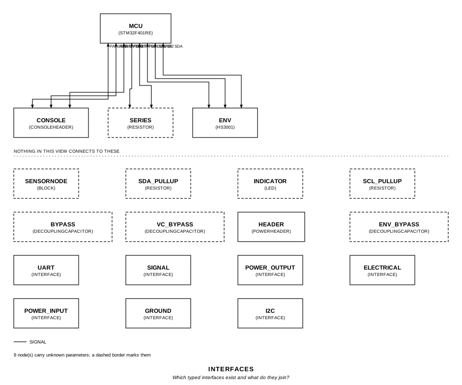
The MCU’s three links: I2C1 to the sensor, USART2 to the console header, and the status signal to the LED’s series resistor.
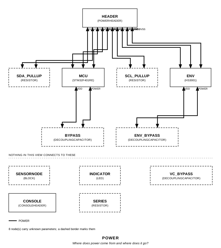
The rail from the header to both parts and the pull-ups, with each part’s decoupling hung off its own supply pins. The VC capacitor joins the sensor’s VC pin to ground and touches no supply pin, so this view leaves it below the rule.
Running it
Section titled “Running it”fang check examples/sensor_node/sensor_node.pyfang netlist examples/sensor_node/sensor_node.pyfang view examples/sensor_node/sensor_node.py interfaces -o interfaces.svgfang verify examples/sensor_node/sensor_node.py # needs renode 1.17.0fang emulate examples/sensor_node/sensor_node.py --bundle-only -o bundlesmake -C examples/sensor_node/firmware # needs arm-none-eabi-gccThe whole program
Section titled “The whole program”"""An STM32F401RE reading an HS3001 over I2C1, with a console on USART2.Show 12 more lines
It records two facts the other examples cannot state: which of themicrocontroller's controllers a port is, with the alternate function thatroutes each signal to its pin, and the address the sensor answers on. Bothdecide whether the firmware meets a working bus, and both are read off thevendors' datasheets and cited, never inferred from a pin's name.
The MCU is reduced to the pins this board uses. Three of its four VDD/VSSpairs and their capacitors, the 4.7 uF bulk capacitor, VCAP_1, VDDA, VBAT,NRST and BOOT0 are left out, so this is a board for the checks and for runningfirmware against, not one to send to fabrication."""
from fang.emulation import ( Absent, At, Count, EmulationModel, Emulates, Firmware, FirstAt, I2CRead, PinConfig, Rises, UartValue,)from fang.interfaces import AF, I2CPort, Pin, PinMap, PowerIn, PowerOut, UARTPortfrom fang.lang import ( Electrical, Ground, Ohm, Parameter, Part, Signal, System, UnitLiteral, V, degC, kHz, kOhm, ms, nF, require, s,)from fang.parts import LED, DecouplingCapacitor, Resistorfrom fang.rationale import Cites, Requires
#: Dimensionless, for a bus address: a count, not a measure.addr = UnitLiteral("1")#: Dimensionless, for events counted in an emulated run.count = UnitLiteral("1")
#: The two datasheets every number below was read from.ST = "SRC-DS-STM32F401" # ST DS10086, STM32F401xD/xE, Rev 5RENESAS = "SRC-DS-HS3XXX" # Renesas R36DS0045EU0101, HS3xxx, Rev 1.01
class STM32F401RE(Part): """The STM32F401RE in LQFP64, with I2C1 and USART2 as named instances.Show 6 more lines
I2C1 can reach PB8/PB9 or PB6/PB7, both at AF4; the pair is a recorded decision, PB8/PB9 preferred. USART2 is PA2/PA3 at AF7. Each port names its instance, so a connection to `i2c1` cannot land on I2C2's pins, and each candidate carries the selector the firmware has to write. """
designator_prefix = "U"
power = PowerIn(voltage=3.3 * V) # Levels at VDD = 3.3 V: VIH 0.7 VDD and VIL 0.3 VDD for an FT pin; VOL # 0.4 V and VOH VDD - 0.4 V for a CMOS output at 8 mA. Fast mode is the # most the I2C controller supports. i2c1 = I2CPort( peripheral="I2C1", voltage=3.3 * V, vih_min=2.31 * V, vil_max=0.99 * V, vol_max=0.4 * V, bit_rate=400 * kHz, ) usart2 = UARTPort( peripheral="USART2", voltage=3.3 * V, voh_min=2.9 * V, vol_max=0.4 * V, vih_min=2.31 * V, vil_max=0.99 * V, ) status = Signal()
# Vendor names and LQFP64 pad numbers, kept apart: the pad number is the # package's, and nothing derives a port pin from it. VDD = Pin("VDD", role="power", number="64") VSS = Pin("VSS", role="ground", number="63") PA2 = Pin("PA2", role="data", number="16") PA3 = Pin("PA3", role="data", number="17") PA5 = Pin("PA5", role="data", number="21") PB6 = Pin("PB6", role="clock", number="58") PB7 = Pin("PB7", role="data", number="59") PB8 = Pin("PB8", role="clock", number="61") PB9 = Pin("PB9", role="data", number="62")
pinout = Cites( "LQFP64 pins: PA2 16, PA3 17, PA5 21, PB6 58, PB7 59, PB8 61, PB9 62, " "VSS 63, VDD 64; PA2, PA3, PA5 and PB6 to PB9 are 5 V tolerant (FT) I/O", document=ST, locator="DS10086 Rev 5, table 8 (pin definitions), pp. 38-44; " "figure 12 (LQFP64 pinout), p. 35", ) af_table = Cites( "I2C1_SCL is AF4 on PB6 and PB8, I2C1_SDA is AF4 on PB7 and PB9; " "USART2_TX is AF7 on PA2 and USART2_RX is AF7 on PA3", document=ST, locator="DS10086 Rev 5, table 9 (alternate function mapping), pp. 45-46", ) io_levels = Cites( "FT I/O, 1.7 V <= VDD <= 3.6 V: VIL max 0.3 VDD, VIH min 0.7 VDD. " "CMOS port at IIO = 8 mA, 2.7 V <= VDD <= 3.6 V: VOL max 0.4 V, " "VOH min VDD - 0.4 V", document=ST, locator="DS10086 Rev 5, table 54 (I/O static characteristics), p. 91; " "table 55 (output voltage characteristics), p. 94", ) i2c_rate = Cites( "The I2C interface supports standard mode, up to 100 kHz, and fast " "mode, up to 400 kHz", document=ST, locator="DS10086 Rev 5, section 6.3.19 (I2C interface characteristics), p. 98", ) part_number = Cites( "STM32F401RET6 is 64 pins (R), 512 Kbytes of Flash (E), LQFP (T), " "-40 to 85 C (6)", document=ST, locator="DS10086 Rev 5, table 87 (ordering information scheme), p. 132; " "table 88 (device order codes), p. 133", )
pinmap = PinMap( {"power.vcc": "VDD", "power.gnd": "VSS", "status.line": "PA5"}, evidence="pinout", ) # Candidates in preference order, each with the alternate function that # routes the signal to it. The lowering picks one pair and records why. peripherals = PinMap( { "i2c1.scl": {"PB8": AF(4), "PB6": AF(4)}, "i2c1.sda": {"PB9": AF(4), "PB7": AF(4)}, "usart2.tx": {"PA2": AF(7)}, "usart2.rx": {"PA3": AF(7)}, }, evidence="af_table", )
class HS3001(Part): """Renesas's HS3001 humidity and temperature sensor, at its fixed address.Show 5 more lines
The datasheet states no input or output logic levels for SCL and SDA, so none is written here, and the logic-level check over the bus is undecided rather than passed on a number nobody read. """
designator_prefix = "U"
power = PowerIn(voltage=3.3 * V) # 0x44 is the only address the part answers on; there is no strap pin. # The pull-ups to VDD are the ones its application circuit requires. i2c = I2CPort( address=0x44 * addr, voltage=3.3 * V, bit_rate=400 * kHz, pull_up_resistance=2.2 * kOhm, pull_up_supply=3.3 * V, ) vc = Electrical()
SCL = Pin("SCL", role="clock", number="1") SDA = Pin("SDA", role="data", number="2") VC = Pin("VC", role="unknown", number="3") VDD = Pin("VDD", role="power", number="4") # Do not connect: declared so the pinout is whole, and left unconnected. NC = Pin("NC", role="unknown", number="5") VSS = Pin("VSS", role="ground", number="6")
fixed_address = Cites( "The HS3xxx series I2C address is 0x44, and the device responds only " "to this 7-bit address; a custom address is available on request", document=RENESAS, locator="R36DS0045EU0101 Rev 1.01, section 7.2 (sensor slave address), p. 10", ) pinout = Cites( "6-LGA, 3.0 x 2.41 mm: 1 SCL, 2 SDA, 3 VC (0.1 uF to ground), 4 VDD, " "5 NC (do not connect), 6 VSS", document=RENESAS, locator="R36DS0045EU0101 Rev 1.01, section 1.2 and figure 1 " "(pin assignments), p. 4", ) application = Cites( "Pull-up resistors to VDD are required on SCL and SDA, 2.2 kOhm typical; " "0.1 uF from VC to ground and 0.1 uF from VDD to ground", document=RENESAS, locator="R36DS0045EU0101 Rev 1.01, section 6, figure 13 " "(application circuit), p. 9; section 7, p. 10", ) i2c_rate = Cites( "SCL clock frequency up to 400 kHz", document=RENESAS, locator="R36DS0045EU0101 Rev 1.01, table 1 (I2C timing parameters), p. 10", )
pinmap = PinMap( { "power.vcc": "VDD", "power.gnd": "VSS", "i2c.scl": "SCL", "i2c.sda": "SDA", "vc.line": "VC", }, evidence="pinout", )
class PowerHeader(Part): """Where the 3.3 V rail arrives. What supplies it is not this board's."""
designator_prefix = "J"
dc = PowerOut(voltage=3.3 * V)
VCC = Pin("VCC", role="power", number="1") GND = Pin("GND", role="ground", number="2")
pinmap = PinMap({"dc.vcc": "VCC", "dc.gnd": "GND"})
class ConsoleHeader(Part): """Where USART2 leaves the board, for a 3.3 V serial adapter.Show 5 more lines
A connector passes the board's signals through, so its pins carry the board's names: TXD is what the MCU transmits, and the adapter's cable crosses it. The levels on the far side are the adapter's, and not known. """
designator_prefix = "J"
uart = UARTPort(voltage=3.3 * V) ground = Ground()
TXD = Pin("TXD", role="data", number="1") RXD = Pin("RXD", role="data", number="2") GND = Pin("GND", role="ground", number="3")
pinmap = PinMap({"uart.tx": "TXD", "uart.rx": "RXD", "ground.gnd": "GND"})
class SensorNode(System): """A sensor on I2C1, a console on USART2 and a status LED on PA5.Show 7 more lines
The firmware in `firmware/` is run against this board in Renode, and two questions are asked of it: whether it reads the sensor, reports what it read and shows a good reading on the LED, and whether it keeps running and shows the fault when the sensor is missing. Each is a requirement the board is verified against, by emulation, through the commit gate. """
sensor_ready = Requires( "Within 200 ms of reset the firmware reads the HS3001, reports the " "temperature it read on the console, and blinks the status LED slowly " "while readings succeed", validation="emulation", ) survives_missing_sensor = Requires( "With the HS3001 missing the firmware keeps running and blinks the " "status LED fast", validation="emulation", )
first_read = Parameter("s", description="when the firmware first reads the sensor") reported = Parameter("degC", description="the temperature the firmware prints") slow_blinks = Parameter("", description="status LED rises between 1 s and 2 s, sensor present") mux_mismatches = Parameter("", description="I2C1 pins configured otherwise than the board requires") fast_blinks = Parameter("", description="status LED rises between 1 s and 2 s, sensor missing")
# The sensor is at 25 degC from reset. The pull-ups, the LED's resistor and # the console header share nets with the pins the question touches and # carry no emulation model, so they are named as abstracted. startup = Emulates( "sensor_ready", run_until=2 * s, stimuli=[At(0 * ms, "env.temperature", 25 * degC)], measures={ "first_read": FirstAt(I2CRead("env")), "reported": UartValue("mcu.usart2", prefix="temp=", unit=degC), "slow_blinks": Count(Rises("mcu.status"), within=(1 * s, 2 * s)), "mux_mismatches": PinConfig("mcu.i2c1"), }, abstracted=("scl_pullup", "sda_pullup", "series", "console"), ) sensor_missing = Emulates( "survives_missing_sensor", run_until=2 * s, faults=[Absent("env")], measures={"fast_blinks": Count(Rises("mcu.status"), within=(1 * s, 2 * s))}, abstracted=("scl_pullup", "sda_pullup", "series"), )
decoupling = Cites( "Each VDD/VSS pair is decoupled with ceramic capacitors close to the " "pins; the scheme shows 6 x 100 nF and 1 x 4.7 uF across the VDD pins", document=ST, locator="DS10086 Rev 5, figure 18 (power supply scheme), section 6.1.6, p. 57", )
header = PowerHeader(package="PinHeader_1x02_P2.54mm") mcu = STM32F401RE(package="LQFP-64") env = HS3001(package="LGA-6") console = ConsoleHeader(package="PinHeader_1x03_P2.54mm")
# 2.2k to VDD, as the sensor's application circuit draws them. scl_pullup = Resistor(resistance=2.2 * kOhm, package="R_0402") sda_pullup = Resistor(resistance=2.2 * kOhm, package="R_0402")
# The one MCU supply pair this board models, decoupled at its pins. bypass = DecouplingCapacitor(capacitance=100 * nF, package="C_0402") # The sensor's two, from its application circuit. env_bypass = DecouplingCapacitor(capacitance=100 * nF, package="C_0402") vc_bypass = DecouplingCapacitor(capacitance=100 * nF, package="C_0402")
series = Resistor(resistance=1 * kOhm, package="R_0402") indicator = LED(package="LED_0603")
def __init__(self, **overrides): super().__init__(**overrides) # The selection lands on the instance, not the class template. self.mcu.select("STMicroelectronics", "STM32F401RET6", datasheet=ST) self.env.select("Renesas", "HS3001", datasheet=RENESAS) # What the emulator runs: fang's F401 platform model, the firmware # beside this program, and Renode's own HS3001 model. self.mcu.add_trait(EmulationModel(source="fang:stm32f401re")) self.mcu.add_trait(Firmware("firmware/elf/sensor_node.elf", target="stm32f401re")) self.env.add_trait(EmulationModel(source="renode:Sensors.HS3001"))
def architecture(self): self.header.dc >> self.mcu.power self.header.dc >> self.env.power
# One connection, one controller: every signal comes from i2c1's # candidates, and the pin connections carry AF4. self.mcu.i2c1 >> self.env.i2c self.header.dc.vcc >> self.scl_pullup.p1 self.scl_pullup.p2 >> self.mcu.i2c1.scl self.header.dc.vcc >> self.sda_pullup.p1 self.sda_pullup.p2 >> self.mcu.i2c1.sda
# The header passes USART2 through; PA2 and PA3 carry AF7. self.mcu.usart2 >> self.console.uart self.header.dc.gnd >> self.console.ground
self.mcu.status >> self.series.p1 self.series.p2 >> self.indicator.p1 self.indicator.p2 >> self.header.dc.gnd
self.mcu.power.vcc >> self.bypass.p1 self.mcu.power.gnd >> self.bypass.p2 self.env.power.vcc >> self.env_bypass.p1 self.env.power.gnd >> self.env_bypass.p2 self.env.vc >> self.vc_bypass.p1 self.env.power.gnd >> self.vc_bypass.p2
def constraints(self): # 3.3 V / 8 mA: whatever the LED drops, PA5 never sources more than the # current its output levels are specified at. require(self.series.resistance >= 412.5 * Ohm)
# What the firmware has to do, decided by emulation. 0.05 degC allows # the sensor's 14-bit quantization: 25 degC reads back as 25.01. require(self.first_read <= 200 * ms) require(self.reported >= 24.95 * degC) require(self.reported <= 25.05 * degC) require(self.slow_blinks == 1 * count) require(self.mux_mismatches == 0 * count) require(self.fast_blinks >= 4 * count)The files it writes
Section titled “The files it writes”The parts, then the nets and the pads on them.
C1 100 nF Package:C_0402C2 100 nF Package:C_0402C3 100 nF Package:C_0402DS1 LED Package:LED_0603J1 ConsoleHeader Package:PinHeader_1x03_P2.54mmJ2 PowerHeader Package:PinHeader_1x02_P2.54mmR1 2.2 kOhm Package:R_0402R2 2.2 kOhm Package:R_0402R3 1 kOhm Package:R_0402U1 HS3001 Package:LGA-6U2 STM32F401RE Package:LQFP-64Net-(C1-Pad1) C1.1 C2.1 J2.VCC R1.1 R2.1 U1.VDD U2.VDDNet-(C1-Pad2) C1.2 C2.2 C3.2 DS1.K J1.GND J2.GND U1.VSS U2.VSSNet-(C3-Pad1) C3.1 U1.VCNet-(DS1-PadA) DS1.A R3.2Net-(J1-PadRXD) J1.RXD U2.PA3Net-(J1-PadTXD) J1.TXD U2.PA2Net-(R1-Pad2) R1.2 U1.SCL U2.PB8Net-(R2-Pad2) R2.2 U1.SDA U2.PB9Net-(R3-Pad1) R3.1 U2.PA5Every check that ran, and every one left undecided.
UNDECIDED constraint: declared on BLK-42978eb8675aUNDECIDED constraint: declared on BLK-42978eb8675aUNDECIDED constraint: declared on BLK-42978eb8675aUNDECIDED constraint: declared on BLK-42978eb8675aUNDECIDED constraint: declared on BLK-42978eb8675aUNDECIDED constraint: declared on BLK-42978eb8675aUNDECIDED interface_compatibility: logic high margin is undecided on i2c: voh_min unknownUNDECIDED interface_compatibility: logic high margin is undecided on uart: vih_min unknownUNDECIDED interface_compatibility: logic high margin is undecided on uart: voh_min unknown17 checks, 0 failed, 9 undecidedWhat the elaborated graph contains, by entity kind.
1 block 11 component 40 connection 7 constraint 4 decision 10 evidence 7 interface 34 pin 24 port 2 requirement 2 verification 142 totalsnapshot sha256:aca66030ef6b081a28f85f582734528421ac3f66be5be80ceba982f30a319beaAll of it, including the KiCad netlist, is in
examples/sensor_node/out/. Rebuild it with:
fang build examples/sensor_node/sensor_node.py